It’s been a challenging time for businesses generally, and particularly in the United Kingdom, with Brexit in many cases adding cost and time to trading, and Covid-19 restricting travel and networking.
So it seemed an appropriate time to launch a new varient of the Yellows Best Limited website, now additionally utilising “.co.uk” as a signifier of commitment to our home market location.
Keeping Customers Operational
The new YellowsBest.co.uk promotes the same blend of Services and Solutions for “Keeping Customers Operational”, but presented in a different and modern single-page layout, making it particularly mobile device-friendly where ‘vertical scrolling’ is more appealing than using the traditional ‘horizontal tabbed’ layout.
We hope this provides Customers old and new with a welcome alternative, though the original YellowsBest.com will continue to be maintained, along with it’s associated blog for ‘informal’ views and news updates.
Assisting with your requirements
It would be interesting to receive feedback as to how useful you may find this additional site, and whether there is anything else you’d like to see featured.
Of course, @YellowsBestLtd online content ultimately serves the purpose of highlighting the types of services and solutions we can provide. Customers may therefore be prompted to get in touch to discuss their specific requirements, which we can usually assist with.
Our aim continues to be “Keeping Customers Operational”; understanding requirements and fulfilling them by providing a range of management services and solutions, including:
consultancy, for business development, sales and marketing
technical support, onsite engineering or 24/7 NOC remote assistance
systems supply, including legacy IT servers / workstations
spares for infrastructure, such as telecoms and CCTV cameras
repairs at module and component level, e.g. LED displayboards, PSUs
value recovery through reverse logistics, resale and recycling
As we continue to move forward, we’d very much like to understand what other services and solutions we can provide to our existing Customers, as well as what would be of interest to potential clients. We’re always keen to enhance our range of #business services, increase the #enterprise infrastructure we support and expand our mix of #sustainable solutions we offer for supply and maintenance of new and legacy #technologies and products.
Please get in touch to discuss your challenges; whether you’re implementing new systems or maintaining existing infrastructure to serve your operational business needs. We look forward to hearing from you.
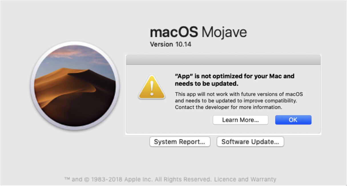
32-bit Application compatibility Issues resulting from macOS updates
Issues have started to appear using existing and older software applications on Apple Macintosh computers with the transition from 32-bit to 64-bit operating systems, commencing with macOS High Sierra 10.13.4, and it’s set to get a whole lot worse!
Current Difficulties
Noticeable problems with applications have surfaced with the update to macOS Mojave.
Strange and unwanted things have crept in. For example:
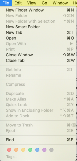
opening a new Finder window causes a new tab to open instead. It’s like the wrong option has been selected – now opening a tab or a window are incorrectly identical. If you want a new Finder window, you need to then select ‘move this tab to a new window’. So suddenly this is a two-stage process
New Finder window opens a New Tab instead
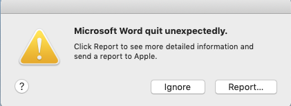
Trying to print from Microsoft Word causes the application to ‘crash’. The work-around for this is its still possible to print by using the toolbar button, instead of selecting ‘print’ from the drop-down menu. But then this doesn’t allow for changing print settings etc.
Microsoft Word quits when trying to print
Promise of worse compatibility problems
This is just the ‘tip of the iceberg’. A whole range of software applications which currently run happily on the Apple Mac are set to become unusable in the next update to macOS. We’re talking about mainstream applications such as Microsoft Office as well as ‘niche’ applications that you may utilise. This appears to represent the biggest shift in software compatibility since the change from Mac ‘Classic’ (OS 9 and before) to Mac OSX, more than 10 years ago.
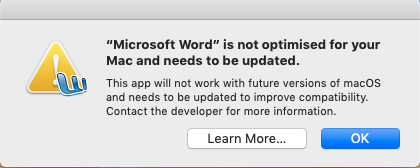
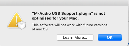
A warning is displayed when a 32-bit application is launched in macOS High Sierra, and in macOS Mojave the alert appears every 30 days.
The official Apple advice is to ‘contact the application developer’. For the average user, that’s unlikely to achieve anything, particularly for mature applications that perhaps are no longer available or don’t have ongoing development. With something like Microsoft Word, then it should be possible to obtain the latest version, but naturally that will require a new purchase and/or an annual subscription.
Purchasing a new version of existing software will be an expensive business to just maintain your existing functionality
Maintenance Decisions
The standard maintenance advice for computers is to upgrade to the latest available version of operating software; that way, security patches are up-to-date, keeping the system secure, with new functionality as well as bug fixes provided, and support for the latest applications.
On this occasion however, it is worth taking a long considered look at the benefits of upgrading verses sticking with your current macOS release. If you haven’t yet moved to macOS High Sierra 10.13.4 or macOS Mojave 10.14 then you may wish to stay where you are for now, particularly if you’re happy with your current applications and functionality, such as Microsoft Word 2008. If you’re contemplating upgrading, either because you ‘must’ for security purposes or need to support a new generation application, then it will be worth taking the time now to review all of your existing software and work out what the upgrade path will be, or find out what the alternatives you could migrate to e.g. Apple’s ‘Pages’ to replace Microsoft Word, etc.
The most worrying situation will be for owners of specific hardware e.g. the M-Audio USB Midi interface, which may not (and never will) have a suitable updated driver software alternative
In such circumstances of uncertain application support, backups are as always essential; ideally you should be in a position to ‘roll-back’, dual-boot and/or run virtual machines to maintain previous applications and functionality.
Consideration should also be given to maintaining a dedicated computer at the existing macOS version, and over time, migrating day-to-day applications (where they can be) to a new computer, keeping the old machine for ‘legacy support’.
Further Assistance
Take a look at the full Apple announcement about the transition to 64-bit technology and how it affects 32-bit apps.
@YellowsBestLtd satisfies new and ‘legacy’ requirements for the maintenance of systems and networks by providing services, such as technical assistance and hardware repairs, and solutions, including the supply of spare part items and software support.
We would be keen to hear from you regarding your operational needs, please get in touch.
The UMUX platform provides carrier-grade reliable multi-service multiplexing and aggregation functions over copper and fibre networks. A variety of voice (POTS, FSX, FSO, ISDN) and data (e.g. G.703, V.11, V,24, V,35) interfaces, SHDSL and Ethernet (including PoE+ and EoS) services are available.
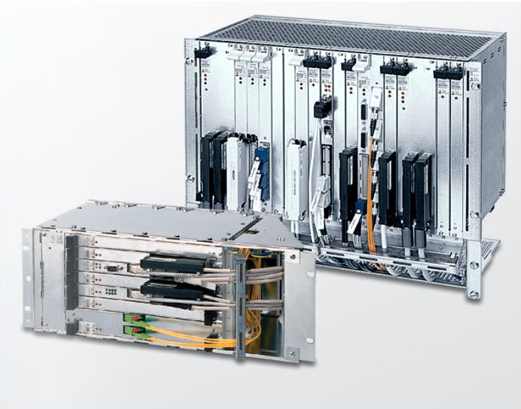
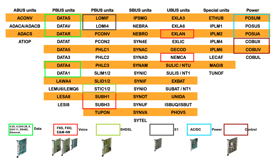
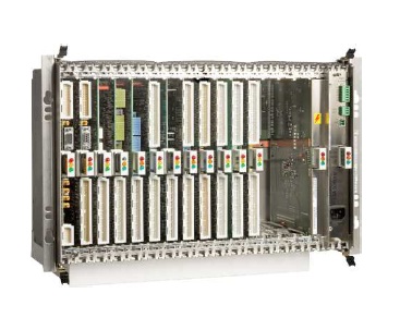
UMUX module range
The modular and flexible housing provided by the UMUX 1500 (8U, 21-slot) and UMUX 1200 (4U, 8-slot) 19” subracks provide the perfect solution for all applications and locations, offering redundant controller and power supplies.
‘Legacy’ telecoms history
The UMUX SDH product portfolio was originally launched 1991 by Ascom, which subsequently became Keymile.
In 2003, by when 70,000 units had been deployed worldwide, the ‘enhanced’ UMUX multiservice access platform was introduced, offering the delivery of ATM, TDM and IP based services from the same platform, with support for IP/Ethernet, ADSL, VoDSL and G.SHDL.
Keymile was sold to ABB in 2017 when the UMUX range was discontinued, and then was acquired in 2019 by DZS.
Continuing to provide operational service
The UMUX, together with the UNEM network management system and ‘sister’ LINERUNNER and MILEGATE products, continues to provide operational service with various global Operator, Utilities and Transport companies.
@YellowsBestLtd supports requirements to maintain these networks by supplying various spare part items from refurbished and surplus stocks in perfect working order.
There follows a list of the main elements that are typically provided, though other items can be provided. Please let us know of any specific requirements you may have. We look forward to being of assistance.
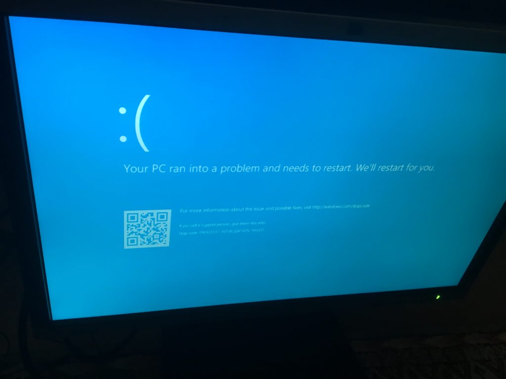
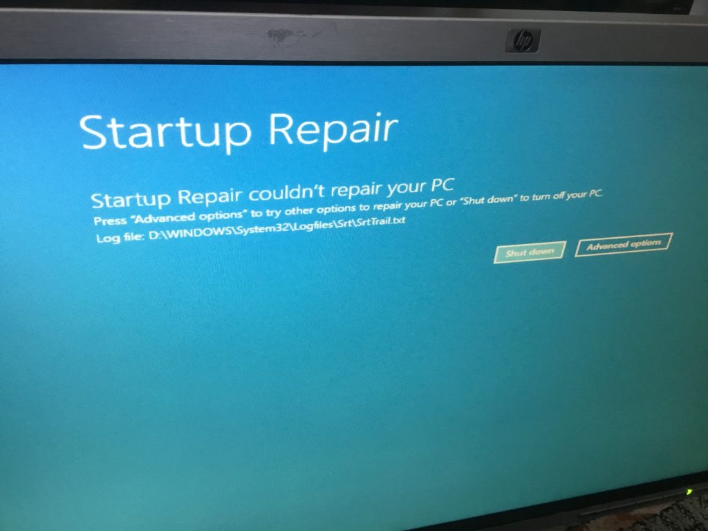
As a result of a PC replacement and upgrade project for Action for Asperger’s, we were presented with a seemingly serviceable Dell Optiplex 755 machine but suffering from a critical failure on power-up, meaning that the computer was unable to boot into windows, preventing use and severely limiting the diagnostics and configuration options.
PC restart
The first step following a reboot was an automatic ‘startup repair’, however, this didn’t result in a fix:
Startup Repair
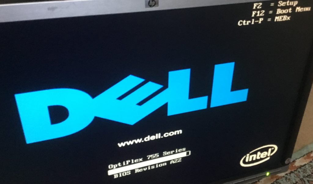
Rebooting again and selecting F2 during the initial boot-up screen:
Boot Up
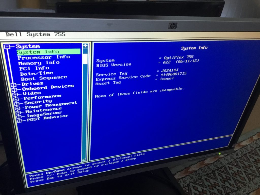
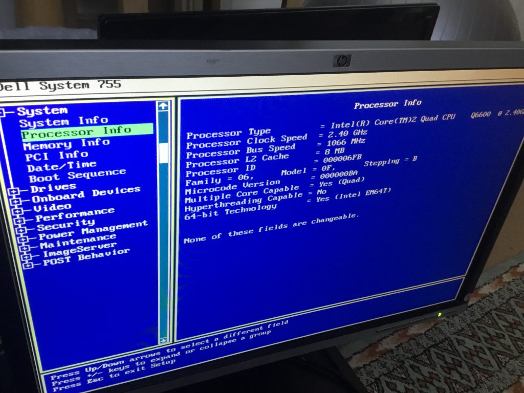
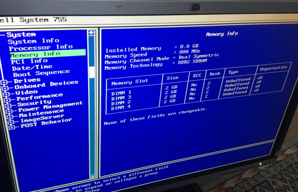
enabled a look at the system information, which indicated that the PC hardware was fine.
System infoProcessor infoMemory info
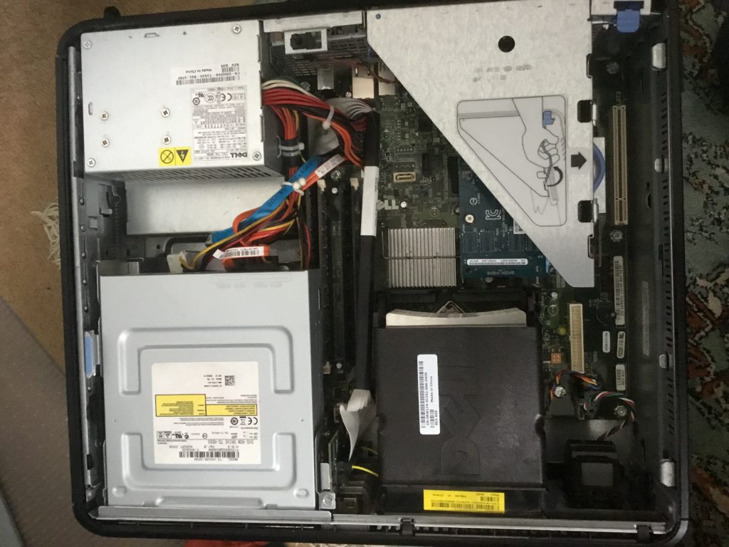
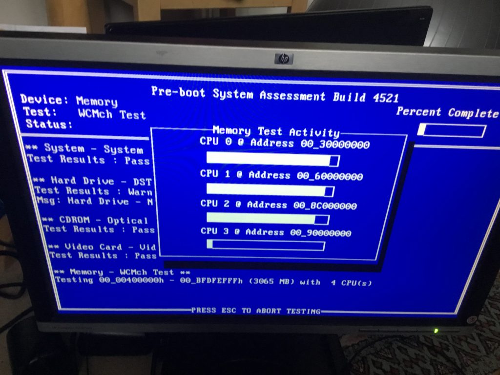
As an extra measure, the internals of the computer were briefly examined, ‘reseating’ components including the video board, memory chips and hard disk and then the system test run to verify all was well.
InternalTest
It was concluded therefore that the PC hardware was not the cause of the difficulties, and that the Windows installation was severely compromised.
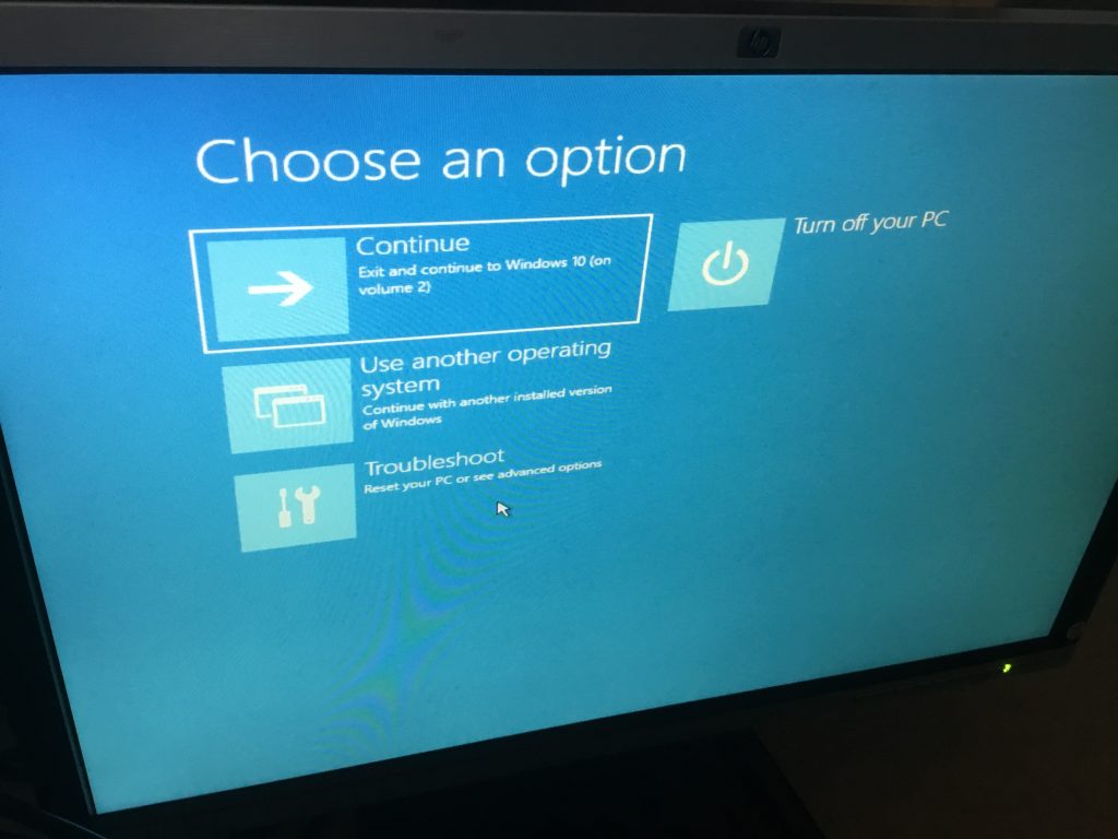
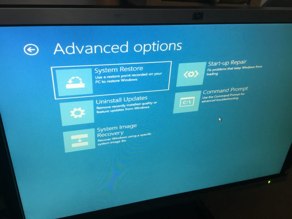
From the bootup, troubleshooting was selected
Choose an option
From the ‘advanced options’, the Command Prompt was accessed.
Advanced options
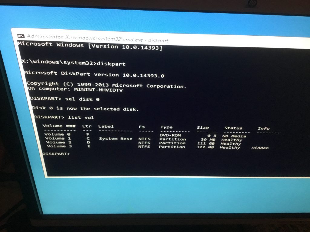
Using these commands:
DISKPART
SEL DISK 0
LIST VOL
It was possible to view and confirm the drives and their assigned letters.
Diskpart
Extra information was provided using this command:
wmic logicaldisk list brief
Progress was further hampered by the internal DVD/CD drive not being recognised on boot-up, in its place an external DVD drive was connected.
Rebooting and pressing F12 on power up enabled the adjustment of the Boot priority, selecting the DVD drive first.
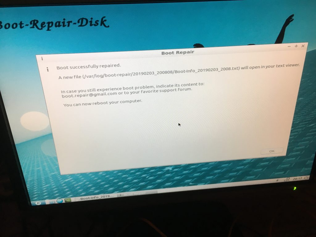
A copy of the Boot Repair Tool by yannubuntu was next downloaded and a boot-repair-disk created
This was run from boot and gave encouraging results:
Boot Repair Disk
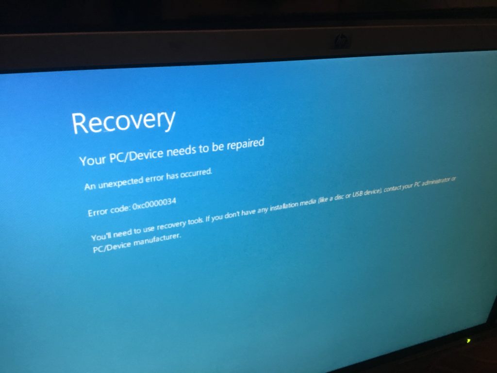
Alas, these steps hadn’t cured the problems, now a further critical error message was displayed:
Recovery
Consequently, using the Microsoft USB/DVD Download Tool, a Windows 10 install disk was created (confusingly the site specifies Windows 7, but it works fine for Windows 10)
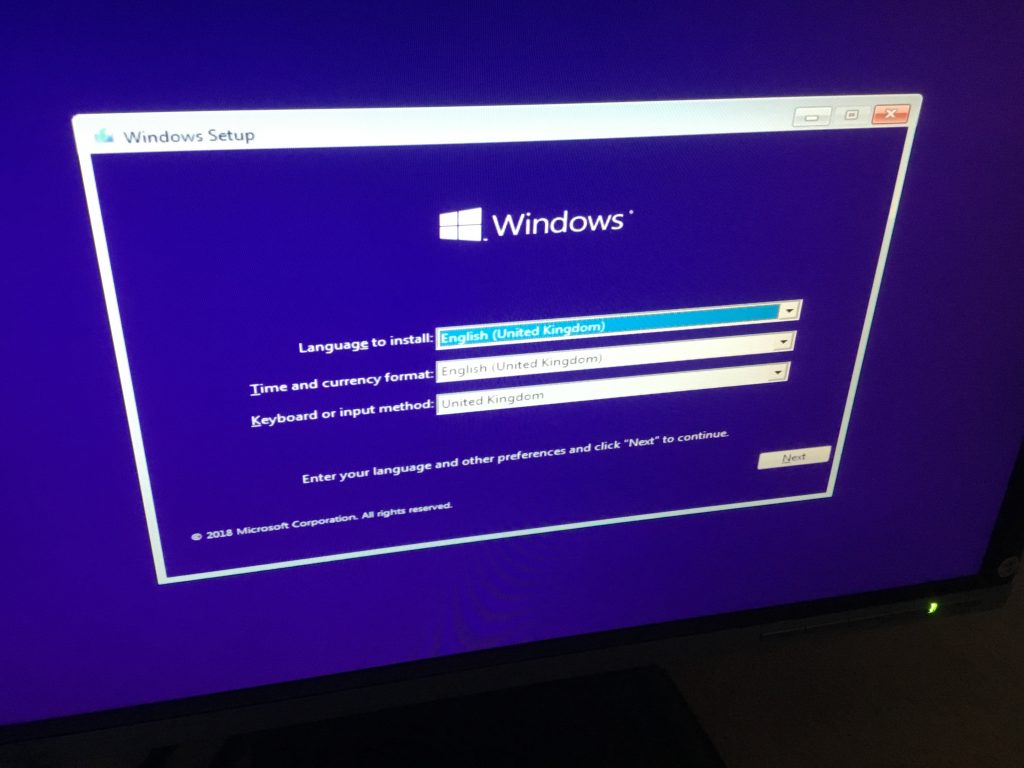
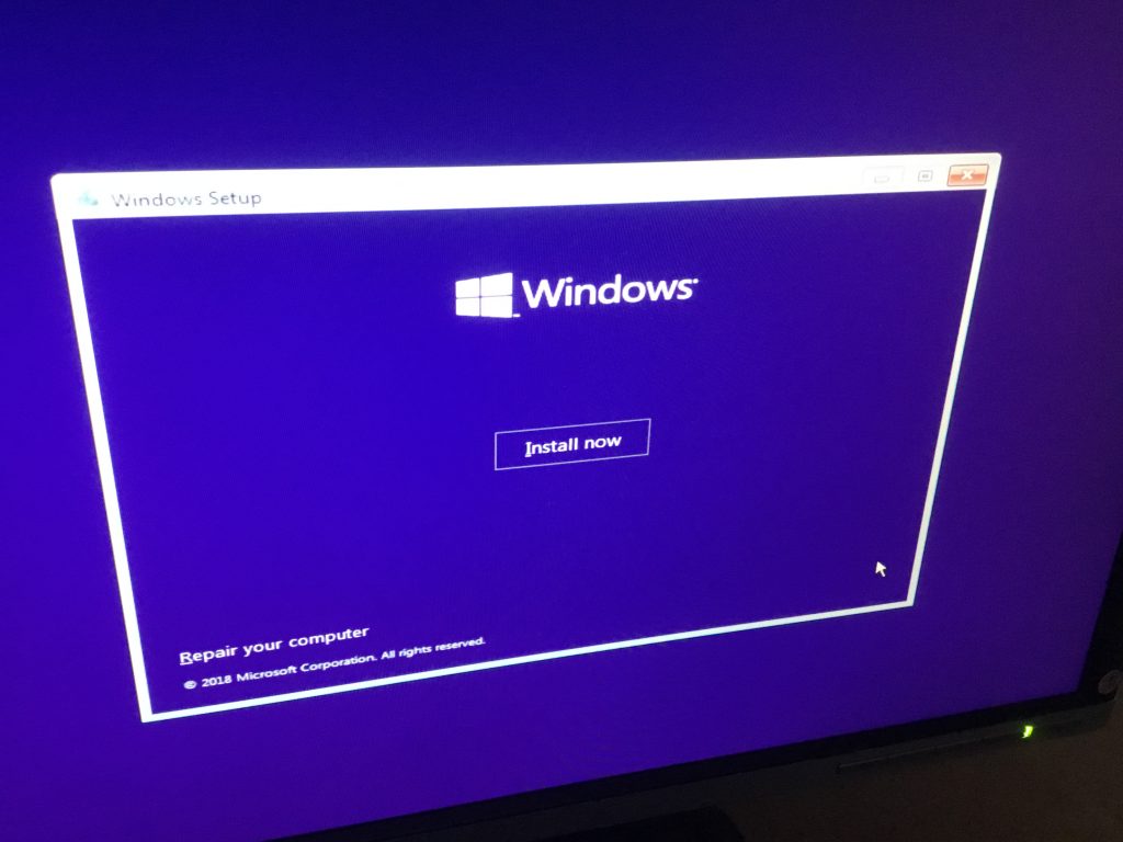
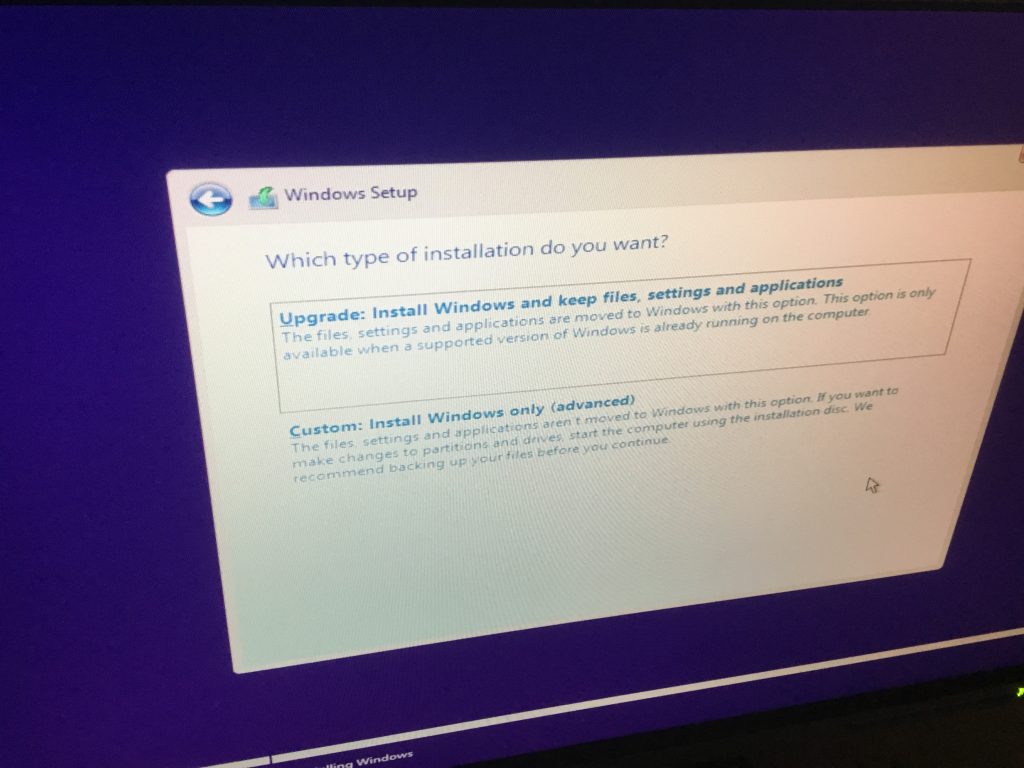
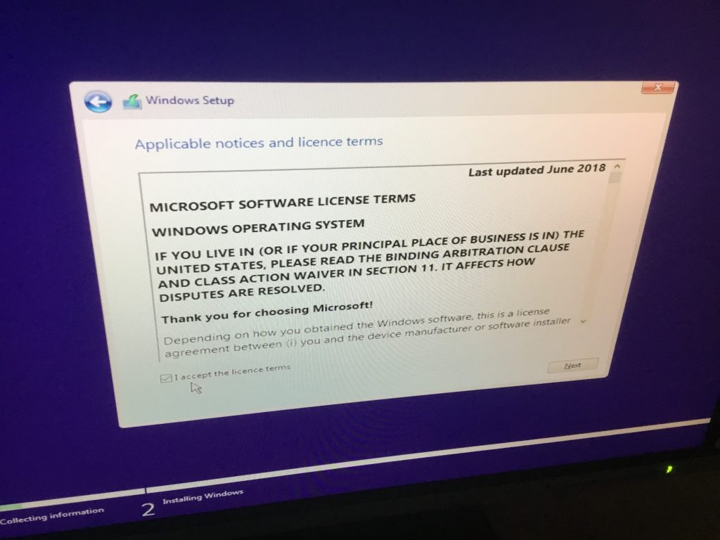
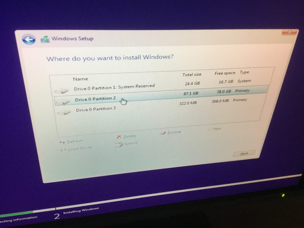
This was booted and the appropriate selections made for a fresh installation of Windows 10:
Windows Setup Windows Install nowWindows type of installationWindows operating system selectionActivate WindowsApplicable notices and licence termsPartition choice
At this point, it was found necessary to delete the old windows partition, extend a different partition and create a new partition in order to be able to commence the windows installation.
Partition selection
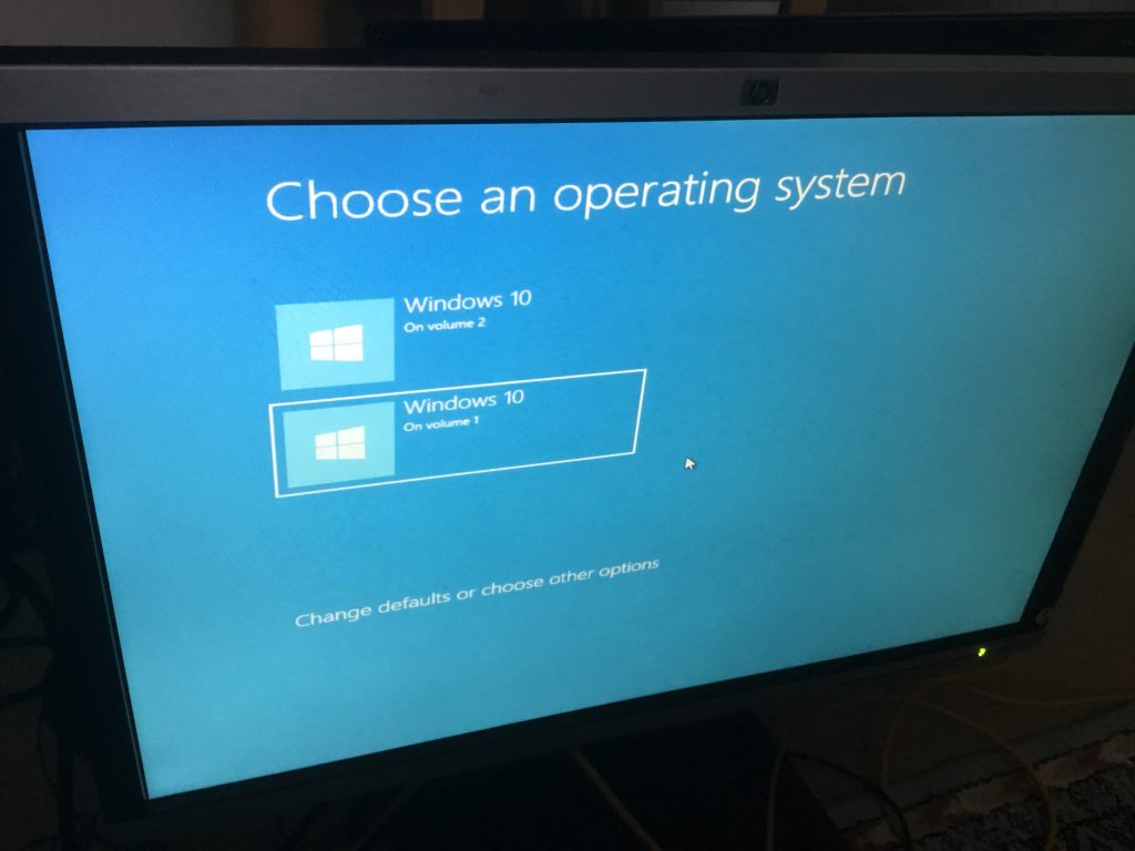
It did however then allow the installation of Windows onto the other partition, meaning that two bootable volumes were created. Might be useful for future upgrades or troubleshooting.
Choose OS
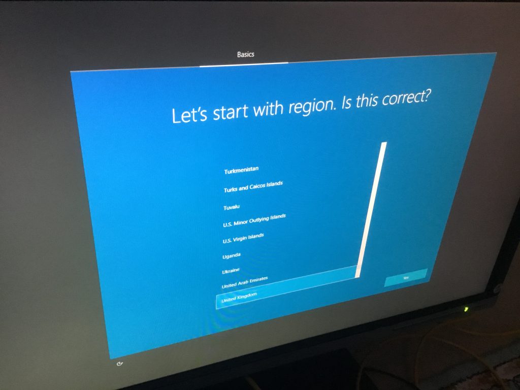
Just the straightforward matter left of completing the user configuration of the operating system ready for use.
Choose region
All done, pleasing to conclude that the critical issues with this PC could be resolved through software corrections alone!
@YellowsBestLtd provides professional Management Services for Business Development activities and Enterprise Support of Infrastructure. We source Solutions for Sustainable Systems maintenance, equipment Technologies and telecoms and other Products to enhance operations.
We’re always keen provide whatever is needed, so please let us know anything you require.
The Nokia ‘Dynanet’ family of PDH Transmission telecoms products has served customers well for the last 20+ years, and indeed some networks continue providing good operational service.
Dynanet Subtrack
@YellowsBestLtd has supported requirements to maintain these networks by supplying various spare part items from refurbished and surplus stocks in perfectly working order.
However, demand has recently reduced and warehouse space is needed, so now the time has come to recycle / dispose of a large proportion of the remaining equipment. Consequently, there remains a short-term opportunity to obtain any items still required to maintain existing deployed infrastructure, before the products are gone.
Here is a stock list of the main items currently available, though there may be a few additional parts that can be supplied. Hence, please check and if you do have any requirements, please let us know – before it’s too late! We look forward to hearing from you.
Part Number
Description
24204
TPSO H/W Module
CC 24002
DB2 Branching Unit, B2 2×2 Mb/s 75 ohm
CC 24011
DB2 2 Mb/s Switching Unit, X2 75 ohm
CC 24101
DN2 Interface Unit (IU2) 2×2 Mb/s 75 ohm
CC 24111
DN2 Control Unit (CU) 75 ohm
CF 24186
DN2 19″ Subrack
CF 24186.09
DN2 Subrack 19″, grey-L91 EMC
CG 24170
DN2 Bus Power Unit (BPU)
CG 24171
Extended DN2 Bus Power Unit (EBPU)
CU 24013
Data Interface Unit (DIU) 2M, nx64k: G.703/704, 75 ohm
T30506.09
17-slot DYNANET Subrack
T30851.02
Subrack Power Adapter (SPA)
T37870.01
NDM ACM2 19in 17-slot subrack
T37871.01
NDM DN2 19″ 17-Slot Subrack
T37882.01
NDM DC Unit (NDUe)
T37882.02
NDM DC Unit (NDUe)
T37885.01
NDM Ring Generator
T37889.01
NDM Backup Unit (NBU)
T65520.01
ACL2 RM DC Power Gen
T65580.01
ACL2i PF GEN Line Terminal Card
TA 21513
Optical Line Terminal Repeater 2-8 M, 1300 nm LED MM/SM
TA 21516
Optical Line Terminal Repeater 2-8 M, 1300 nm LASER SM
TC 21101
DM34 Mux Card
TC 21301
DM8 Multiplex Equipment, 75 ohm
TC 21705
Supervisory Substation
TC 21710.01
TMS Adapter
TG 21261
Ring Generator 25HZ 15W
TU 21122.5
Data Interface Unit (DIU) 48..64k V.11 10ch
TU 21124
Data Interface Unit (DIU) NX64k V.11/V.35/X.21 2CH