Solar energy – generation & applications – AC vs DC

‘High Voltage’ – transmission & usage

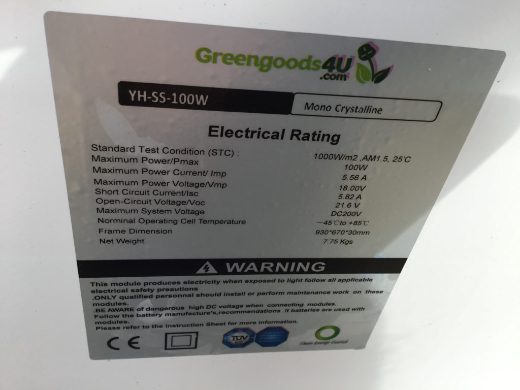
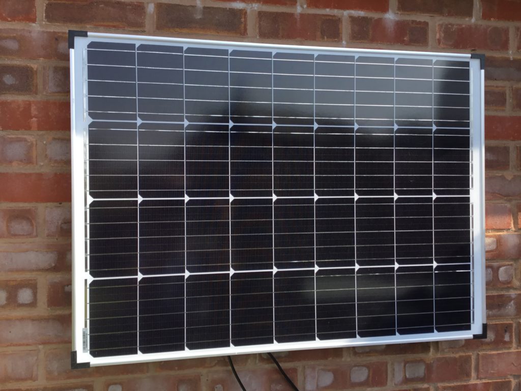
Following on from our recent post on our Solar Power System – On Grid Project, the observation has been made that it’s rather inefficient to generate power as DC electricity, and convert it to a higher AC voltage, before converting it back again to DC to suit many consumer applications.

Voltage multiple conversion

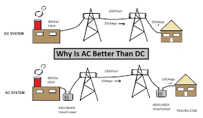
The issue of use of AC or DC is not a new one. Famously, in 1893, Thomas Edison who promoted the generation and use of DC ‘lost’ the battle to George Westinghouse who gained acceptance for the generation of AC at the Chicago World’s Fair, since it was more efficient in long-distance transmission.

This has been the situation for more than a century and still applies with generation at remote power stations and transmission at high AC voltage to feed and satisfy local demand. The 240V (in the UK) AC mains electricity that is delivered to a household is perfectly suitable in this form for domestic high power applications i.e. cooker, washing machine, etc. On the other hand, electricity is used for variety of low-voltage DC devices and gadgets e.g. phones, TVs, computers and so on, contain power adapters converting AC to DC and stepping down to typically 12v or 5v USB. Lighting is traditionally AC, but with advancement in LED technology could be of a lower DC voltage.

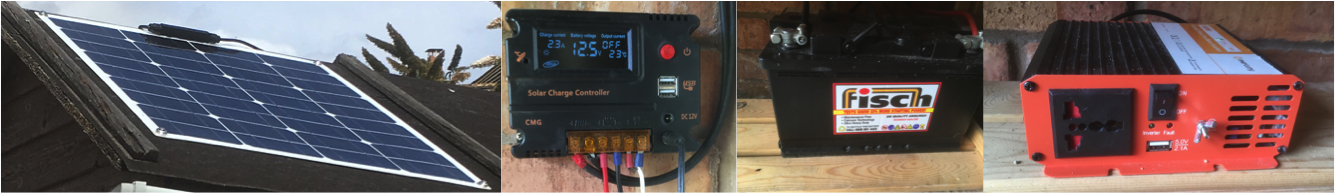
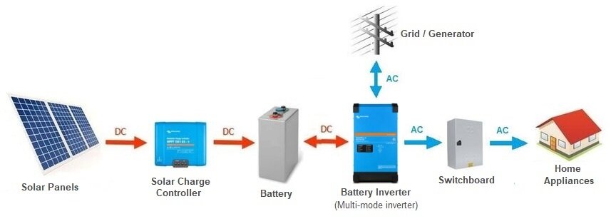
The development of locally generated solar energy changes things somewhat. The generation output is low voltage DC. The majority of this generated electricity is utilised locally. Excess energy can be stored in batteries, which are also low voltage DC. This could be used in this form, but in order for a household to be able to supplement locally generated energy, when the sun doesn’t shine (night time / winter), it still has to be wired to receive AC from the grid-based electricity. Also, to facilitate the export of excess energy (an increasingly valuable benefit of domestic solar power generation), the locally generated electricity must be converted to grid-compatible AC, using an inverter.

It should be the case that houses of the future are designed and built with solar panels on the roof. Indeed, it is now the case they are cheaper that slate, and so the materials and labour charges would be negligible costs if part of the build rather than as an add-on. In which case, the building could be designed with 12V DC and 5V USB supplementary to the 240V AC for mains wiring, feeding appliances directly at the type of voltage they require, eliminating power rectifiers and most voltage converters.

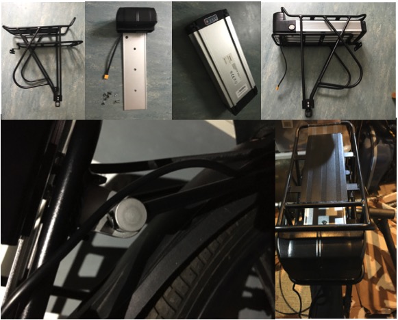
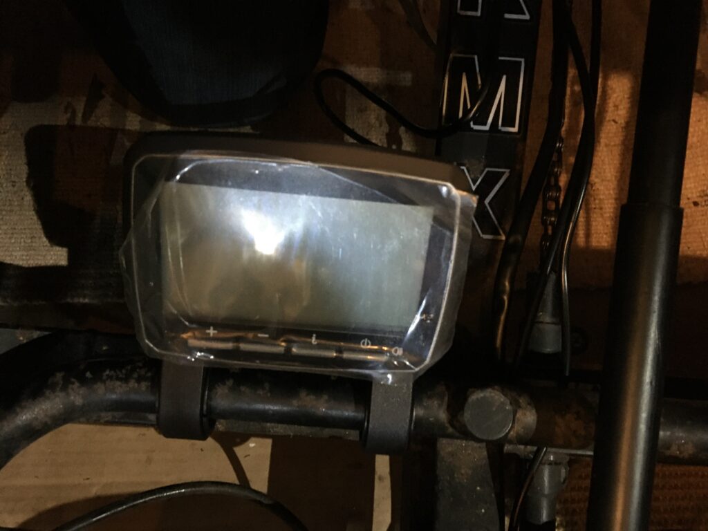
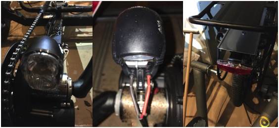
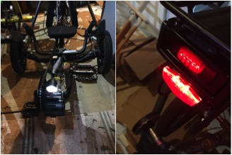
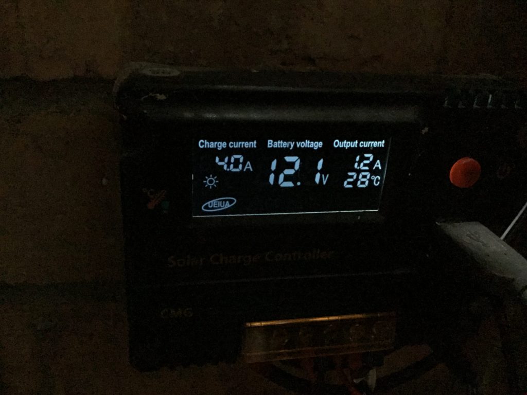
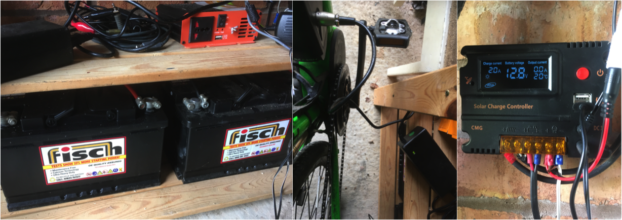
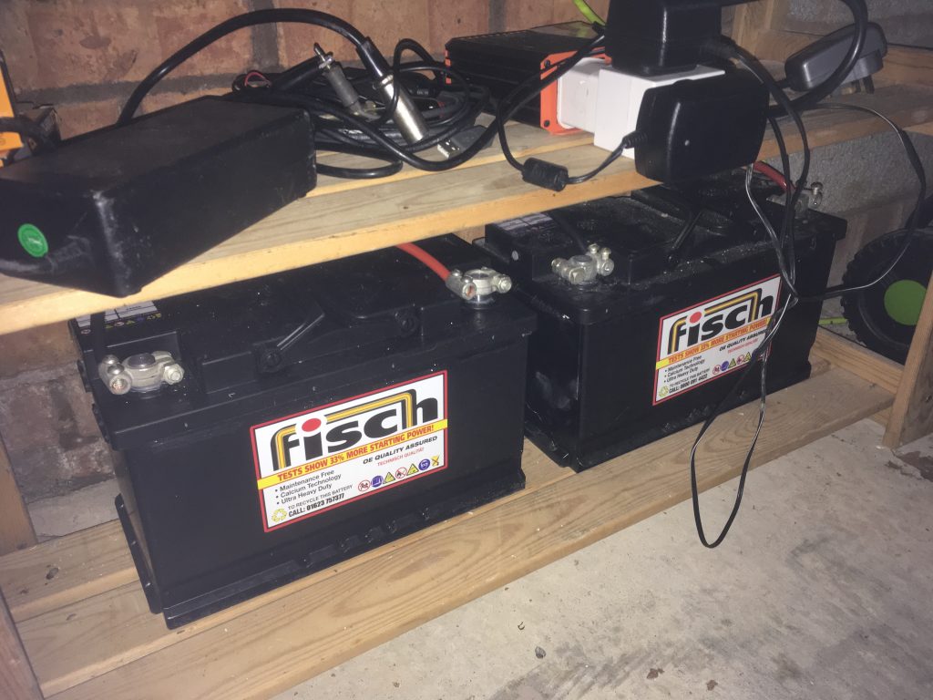
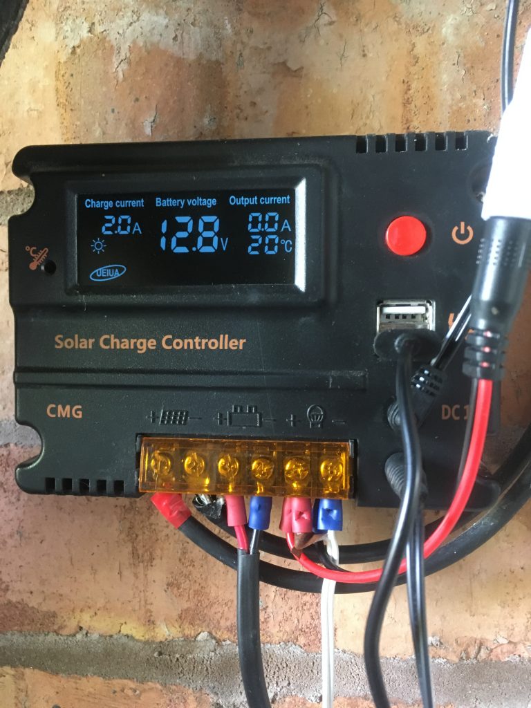
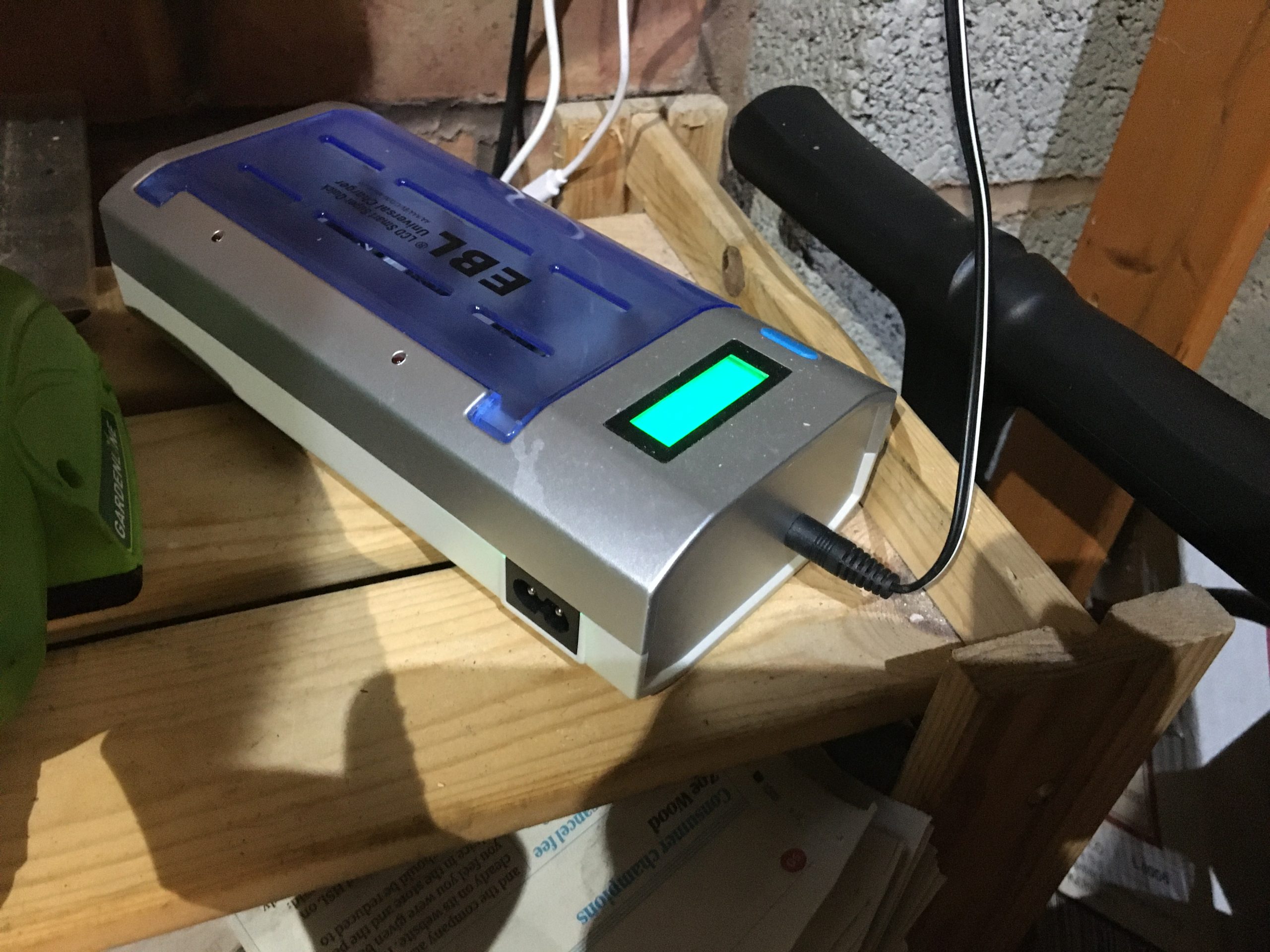
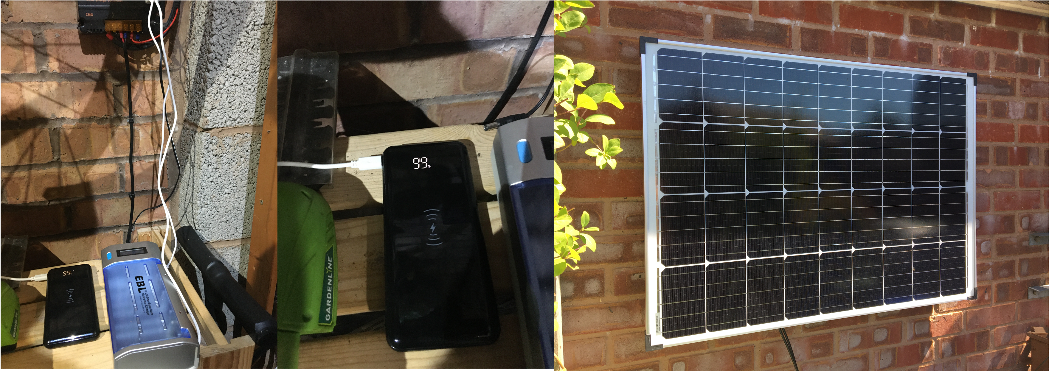
This ‘direct supply’ is already demonstrated in our Solar energy off-grid eBike charger project with the generated supply connected to a AA / AAA / C / D / PP3 battery charger using its 12V DC input (bypassing a 240V AC input, which requires internal conversion). The 12V supply also feeds LED lights without voltage conversion.

Charging batteries from 12V DC Solar Energy

Similarly, the 5V USB outputs of the solar charger controller can charge iPhones and other gadgets.

Solar Charge controller with 5V DC USB sockets

‘Highway to Hell’ – EV charging & V2X

We know that Electric Vehicles (EVs) are going to be increasingly in use and will gradually take over from petrol and diesel engines.

PHEV charging

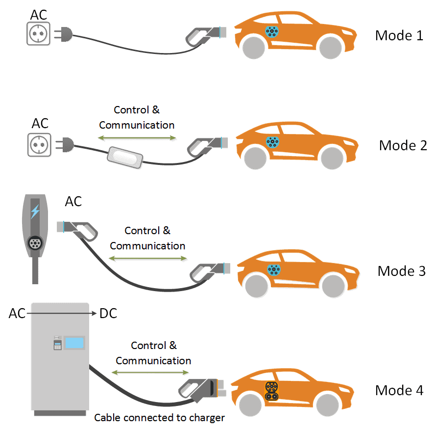
And so the ability to charge these at home will be increasingly important and convenient. Some cars are already of a Plug-in Hybrid Electric Vehicle (PHEV) type, meaning that they can be charged from a domestic UK 240V AC supply for local use. 

Another key development is the concept of EV batteries being used as supplementary storage for a household, so called ‘Vehicle to Home’ (V2H), ‘Vehicle to Building / Business’ (V2B) or ‘Vehicle to Grid’ (V2G) [collectively V2X indicating bi-directional, as opposed to single direction V1G], charging at low demand and discharging when household usage is greater, or to take advantage of higher export pricing.

V2X Charging types

The AC supply is needed to be converted to a DC voltage useable by the car batteries, and similarly the car’s electricity needs converting from DC to AC for household export. There are two ways of achieving this, by having a converter in the charger or the car. But if the premises has its own source of accessible DC power, ideally sourced from locally generated solar energy, then this conversion would be unnecessary.

AC vs DC charging

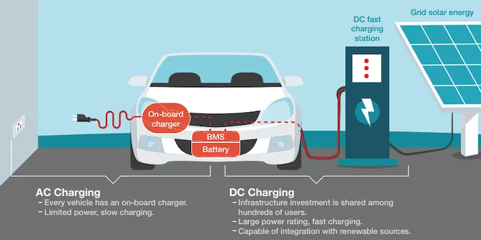
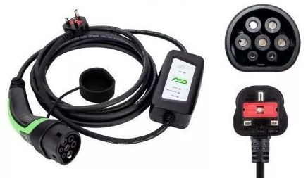
Another issue is that UK 240V AC is limited to 13A supply from standard household sockets (for most domestic use) providing slow charging at 3kW. A dedicated charging point using a UK Type 2 connection is an improvement with direct connection to the mains consumer unit, providing charging at 3.6kWh from a 16V AC supply or 7.4 KW from a 32V AC supply. Faster charging is possible with 11kW from 32A AC supply or faster still with 22kW from 63A AC supply, but these are more expensive, beyond the available power of many households and require a 3-phase supply.

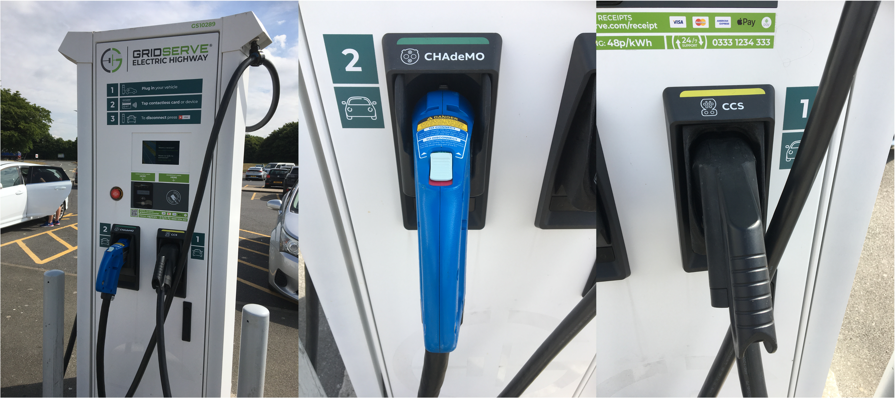
The European Union has specified the Combined Charging System (CCS) standard to permit both AC and DC charging. Much faster and more efficient charging at 100kW and beyond is possible using DC charging, eliminating the conversion in the vehicle. However, this is currently an even more expensive solution and limited to EVs that can accept a compatible DC input. Charging at commercial sites such as motorway service stations offer a variety of standards, including the CCS (Europe), CHAdeMO (Japan), GB/T (China) or Tesla Supercharger (propriety).  

EV charging service station offering both CHAdeMO and CCS standards

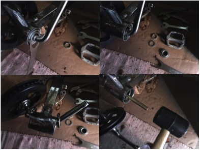
This conversion and compatibility issue is not confined to motor vehicles. As highlighted in the Solar energy off-grid eBike charger project, conversion using an inverter is necessary from the 12V DC power generated from the Solar Panel and stored in the battery, to 240V AC used by the required charger, which then converts again into 36V DC. The problem is not just related to type and size of voltage, as the lithium batteries used require special adapters to perform the charging correctly. It would be possible to produce these fed from a specialist DC adapter, but such chargers are more difficult (and expensive) to obtain, given that the domestic supplies are generally not available in this form and so consequently the demand for these products is not yet there.

‘Thunderstruck’ – Solar powered cooling (mini project)

Given the current heat-wave and the likely-hood of more temperature extremes as a result of climate change, coupled with cost-of-energy crises and possible supply shortages, it seemed appropriate to build another solar power project, this time focusing on powering a cooling fan with energy from the sun.

The concept is relatively straight-forward: using solar energy to assist with cooling. When sitting out and the sun is shining and the temperature is too hot, the sensible thing to do is shelter under some shade. But when there is little-to-no breeze, even in the shade it gets too hot to bare. In which case, a simple fan can help. The one selected was an old, cheap USB model, which provides a limited amount of cooling, but doesn’t require much energy to operate. Also chosen was a small, also old, and low-cost 6V solar panel, which provides just enough energy to power a USB device using a suitable conversion lead.

Solar powered fan

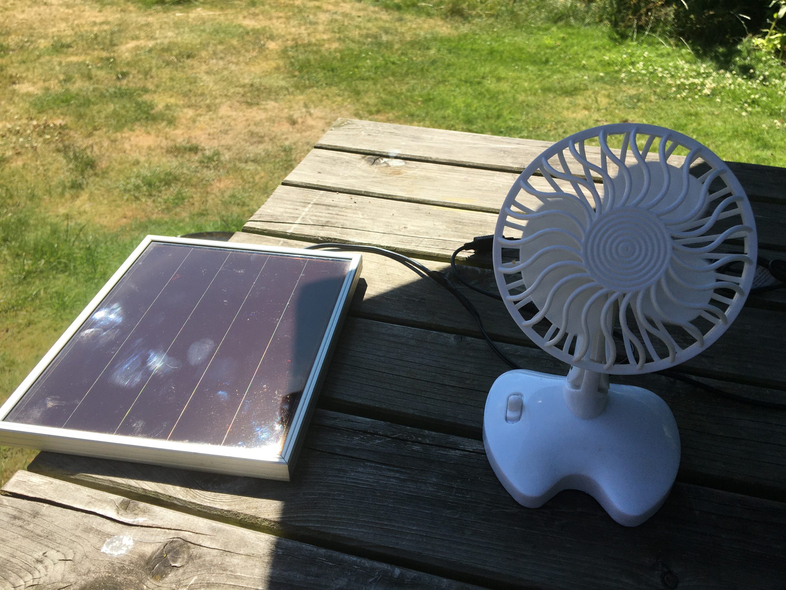
But this isn’t particularly robust since a slight drop in sunshine can stop the set-up working. Hence this has been additionally paired with a battery power bank, which can simultaneously be charged with the solar energy whilst also powering the fan.

Solar powered fan with battery bank

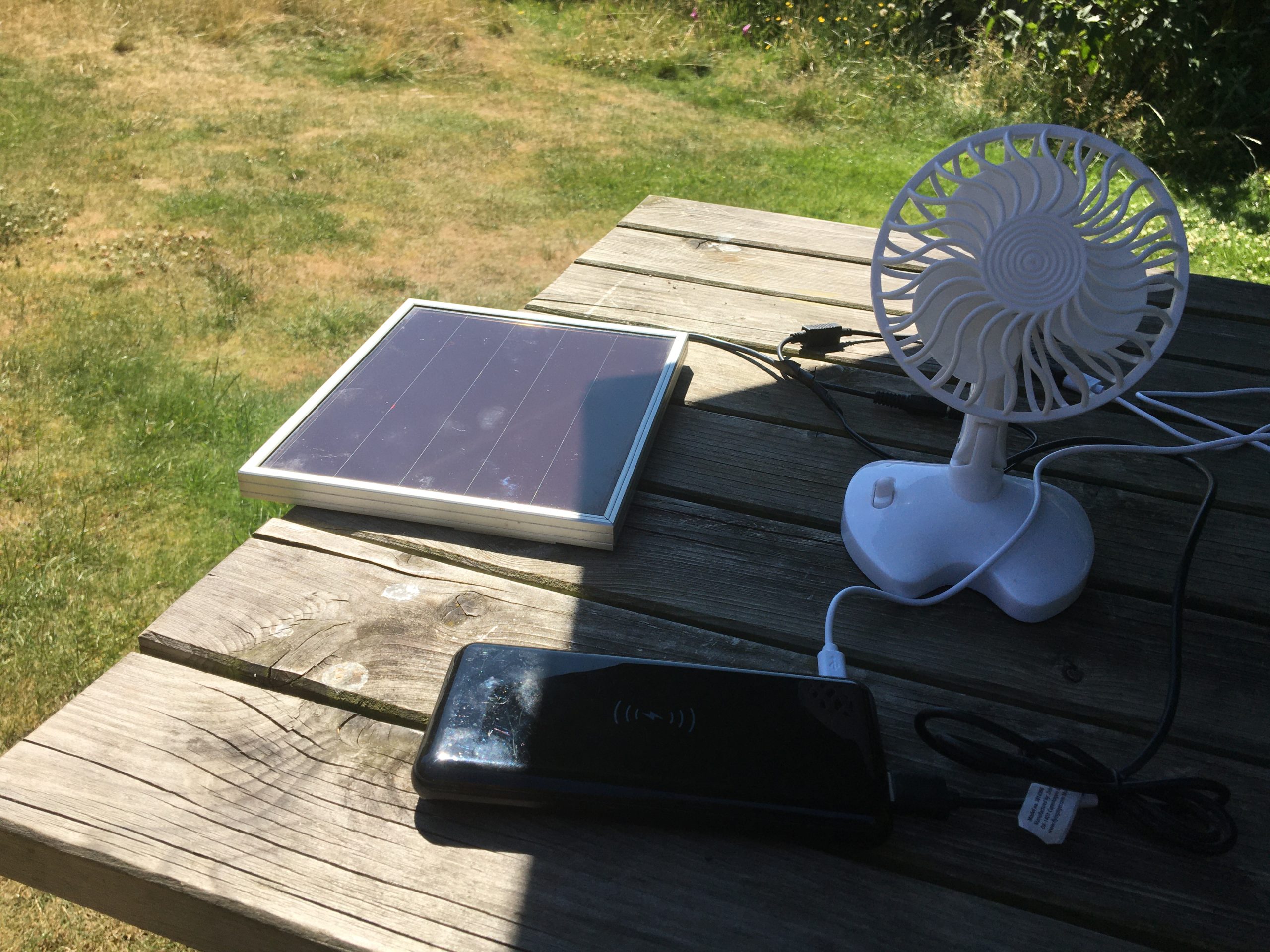
Naturally, the battery pack can be charged separately – ideally powered by locally generated and stored solar energy!

Charging the battery bank from solar energy

‘For those about to Rock’ – the Electric future

Hopefully this has been food for thought into the exciting fast developing world of solar power generation and the electric future. Please get in touch if you have questions, comments or ideas to share. 

@YellowsBestLtd our mission is in “Keeping Customers Operational”. We’re always keen to enhance our range of #business services, increase the #enterprise infrastructure we support and expand our mix of #sustainable solutions we offer for supply and maintenance of new and legacy #technologies and products for our customers. 

Please help us understand your management services or solutions requirements, whether you’re implementing new systems or maintaining existing infrastructure networks to serve your operational business needs. 

eTrike Conversion Project

More fun going electric

With the combination of moving to a more sustainable future along with a fitness drive encouraging people to be more active, one thing growing in popularity is the “eBike”, which supplements the efforts of the rider with a low speed assistance from an electric motor.

eBike

This means you don’t need to be young or super-fit to enjoy getting out and about, with good speeds and longer distances very achievable. And if you want a challenge, you can always switch the assistance off!

Ebikes come ready built to ride away, but an existing machine can be converted.

The three-wheeler challenge 

Given the benefits to two-wheeled cycling from going electric, a similar upgrade to an existing 3-wheeled recumbent trike was called for.

eTrikeOriginal
eTrike awaiting conversion

In principle, this is ‘simply’ a matter of adding an electric motor and a battery, which is indeed what was done, but there were a few challenges along the way.

Step 1: choosing the electric motor location

The first major decision to make when converting or purchasing any electric cycle is the location of the motor; there are three options: front-wheel, rear-wheel or bottom-bracket mount. For the Trike, with its two small forward wheels, front mounting is not possible. The rear option would require the replacement of the wheel with one with a hub motor, and anyway this can be considered an inferior location given that the motor drive is separate from the rider’s push of the pedals. 

Consequently, a bottom-bracket motor was selected, which confusingly on a recumbent trike is not a ‘centre mount’ because it is located at the front, ahead of the front wheel.

Step 2: Motor selection

There are now an expanding number of manufacturers of electric cycle motors, but some of these are only built into new bicycles, and others are prohibitively expensive kits. However, some very affordable Chinese products are available via AliExpress. The selection of the Tongsheng 36V 250W Tsdz2 model from pswpower was made.

TSDZ2
Tongsheng Tsdz2

Given the restriction in the UK of a maximum speed of 15.5 mph for powered assistance and limit of 250W, this unit is perfectly adequate for the intended task.

Step 3: Bottom Bracket ‘special’ fit

The ‘Bottom Bracket’ is the place on all cycles which enables the pedals to rotate, with bearings facilitating the movements of cranks. However, there are many ‘standards’ of different manufacturers models, so getting a motor to fit in place is not necessarily straight-forward. The existing Trike had what is known as an Ashtabula or ‘American’ one-piece crank’ (OPC) Bottom Bracket, whereby the cranks for the pedals on each side are formed from a single unit and uses a 51.3mm bearing cup pressed into the frame.

OnePeiceCrank
American style one-piece-crank


CrankRemoval
Removal of the cranks

Unscrewing the crank retaining nut was aided by use of a Park Tool HCW-18 spanner. One of the pedals was taken off, the bearings teased out, and the crank fed out. Then a brass drift punch bar helped to hammer out the mounting cups from each side.

The difficultly then came that the mounting shaft of the Tsdz2 motor is smaller than the bottom bracket diameter, and is also offset. Fortunately, there is a perfect conversion solution to this problem already available, called the Eccentric BB adapter. This converts the Ashtabula empty shell to standard BSA size 34mm diameter (68mm width), but also is asymmetrical mounting which perfectly accommodates the offset motor shaft. This though is somewhat tricky to source; eventually located at Luna Cycle in CA, USA.

eccentricBBadapter
Eccentric BB American to BSA adapter

Fitting the adapter required careful insertion either side, being a close fit and needing gentle assistance with a mallet, also ensuring that the rotation of two halves lined up.

BBadapter
Eccentric Adapter in place

But once fitted, the motor was slid in and the offset mounting ensured that the shaft located without difficulty or fouling of the frame. The retaining bracket was fitted to the motor and secured with two M5x16 bolts, and then the M33 retaining nut was screwed into place and tightened using the special ring spanner tool supplied with the motor.

MotorInPlace
Securing the Motor

The fixing block was then attached with an M8x40 bolt, and the motor assembly secured in place using the bridge-plate, needed to prevent the possibility of the motor rotating in the crank when being powered in operation.

Step 3: Cranks and pedals

The cranks then fitted to the motor spindles either side. The supplied 170mm long parts were too long for the recumbent machine, being designed for a standard bicycle, and hence a pair of 152mm cranks were sourced, which matched the length of the original ones, which being an all-in-one unit couldn’t be reused. Neither could the pedals, which were a different screw size, and so standard gauge replacements were fitted.

CrankFitment
Fitting the Cranks

These feature a reverse thread for the left-hand side, which therefore was secured by anti-clockwise rotation, whilst the right hand naturally secures clockwise. 

Step 4: Battery fitment

Next came the addition of the 36V 13Ah Lithium-Ion power source. There are various types that can be used on standard bicycles, including down-tube or top-tube units, and bottle-type, but the recumbent trike doesn’t have space for any of these. Instead, it was necessary to add a rear carrier, mounting over the rear wheel, to house a rack mounting battery purchased through eBay from 167-tradeworld-uk. This wasn’t a completely straight-forward fit, as first the rear axle position had to be slightly centralised to accommodate the brackets, and then 16mm pipe clips were needed be added to the frame behind the seat for attaching the front stays to secure the rack. This ensured that the rack didn’t slide or rotate forwards or backwards in use with the weight of the battery.

Rear Rack and Battery

With the rack secured, the purpose-built battery housing was screwed in place on the lower row of the carrier. Then the battery was slid into place and secured with its key lock. Charging of the battery can be made in situ, though it can also be removed for this purpose. This was fully charged using the dedicated mains / 36V power supply adapter.

Step 5: Display mounting

An important part of the electric conversion system is the incorporation of a display, which connects the power and controls the cycling assistance, whilst also providing useful data such as speed, distance and charge remaining.

VLCD5 Display

For this project, a VLCD5 display was chosen, ideal for the purpose. Due the limited room and mounting options, given that there are no high up handlebars or top tube on the recumbent trike, the display was mounted centrally on the low steering crossbar. This was secured via the two horizontal attachment loops, thus in use being positioned between the rider’s legs.

Optional remote button control

The optional remote button control was additionally located on the left handle grip, though this was subsequently found to be of no practical use in operation.  

Step 6: Wiring up

With all the main components in place, all that was left was to make the various wiring connections, starting with linking the battery to the motor. The battery came with an XT-60 socket, whereas the motor has 4mm bullet connectors. Also, due to the forward mounting location of the motor, a cable of approximately 1m was needed to link the parts, converting the connection types in the process. 

Next, the speed sensor was fitted to the left-hand rear wheel stay and accompanying magnet to the spokes, by means of cable ties. This is the means by which the control unit calculates and therefore displays the speed and distance travelled.

Speed Sensor and Wheel Magnet

The attached cable contains a splitter which is used to connect to both the display unit and also optional front and rear lights. Chosen for this purpose was an AXA Echo 15 switch for the front, and a Lynx rack mounting e-bike red LED for the rear, both of which fortunately accepted the 2.8mm mini spade connectors on the wiring harness.

Front and Rear lights

This combination cable was again too short to link the display with the sensor, so an additional 1m speed sensor extension N58B cable was added, this having the required 6-pin male/female connectors to plug into the splitter cable and the corresponding motor connection.

Step 7: Powering up and Configuring

The final step was to switch on the battery using the key and control panel with a press of the power button, and then set about configuring the system parameters.

Display switched on

The wheel size was set to 20 inches, and the distance measurement to miles. The i-button on the display module cycles the modes from ODO (total distance), TRIP, AVG (speed) and TIME. The +/- buttons increase/decrease the selected assistance level from ECO (minimum), TOUR, SPEED to TURBO (maximum).

The front and rear lights can be switched on and off with a short press of the power button. The rear battery light can be additionally manually switched on.

A long press of the power button switches the display off.

Finishing up and testing 

To finalise the build, some cable sheaths were added to tidy up the wiring, and cable ties secured all the leads. The original flag (useful for visibility for such a low-down vehicle) was cable tied in position against the rear rack.

eTrike complete with Flag

The eTrike frame was adjusted for the right seating position. Now was time for a test ride! 

Completed eTrike project

The completed machine performed perfectly well, providing, as most electric cycles do, assistance from a stationary start up to the legal maximum of 15.5 mph. Pedalling effort is still required by the rider, but the effect is to ‘flatten’ hills (and reducing the need for gear changes), making the experience less strenuous and more enjoyable, maintaining a greater average speed and achieving longer ride distances.  

In conclusion, the eTrike conversion was relatively straight-forward, once all the necessary component parts had been identified and sourced. Since recumbent trikes are a somewhat specialised form of cycle, and tend not to be alike, then it is to be expected that a degree of customisation is required to achieve the build of a suitable electric conversion.  

Your transformation projects

@YellowsBestLtd assists customers in developing their business and improving and maintaining their infrastructure. Should you have any requirements or plans, please get in touch to discuss how we may be of assistance. 

Solar Power – eCharger project – UPDATE #2

FIX & UPGRADE – Restoration and increase of Solar Panel energy production

Project Re-cap

The project from 2 years ago, detailed here, built a solar energy charger using these system elements:  Solar Panel, Charge Controller, Battery, Inverter. Last year, an upgrade was performed to increase the batteries to provide more storage capacity, as described in Update #1.

Solar Panel Failure

The system has operated satisfactorily for almost exactly 2 years, but then it was observed that no energy was being produced. After investigation, it was discovered that the solar panel had developed a fault. The panel was a flexible’ model, and by slightly bending it, energy was intermittently produced. Hence clearly there was an internal breakdown of connectivity. 

Solar Panel Replacement & Upgrade

Since a replacement was needed, it was decided to purchase a more robust, ‘fixed (i.e. non-flexible) solar panel, which has a solid frame and securely mount onto a brick wall. Taking advantage of the overall lower cost of fixed vs flexi panels, it was decided to opt for an increase to 100W for the replacement.

RatingInformation
Rating Information

This will bring the advantage of producing more energy during sunny periods, which will compensate for the need to mount the panel on a wall where it receives slightly less direct sunlight hours. 

100W Solar Panel
100W Solar Panel (mounted)

The installation of the replacement panel was relatively straight-forward, using ‘Z-brackets’ to affix to the wall.

zbrackets
Z Brackets

It came with MC-4 connector terminated cable ‘tails’, which were plugged into the existing positive and negative connections.

Connector Block & MC4 tails

Power generation was resumed immediately, with an extremely healthy 4A (roughly double of the previous 50W panel, as expected) confirming the success of the remedy. 

Charge Display
Charge Display

Conclusions

Alas, it transpires that the originally chosen ‘flexi’ type of solar panel is not very ‘robust’ and consequently is only warranted for 1 year. It is somewhat disappointing that only such a short life-span is achieved, especially since it had been mounted on shed-type roof without experiencing disturbance or damage. 

Happily, the replacement ‘fixed’ type of solar panel is warranted for 10 years, so should operate for a considerably longer time. And given that like-for-like it is less expensive, then it is concluded that this should be selected to ensure maximum lifetime and collection capacity for the same outlay. 

@YellowsBestLtd we are always looking to expand our portfolio services for #business development and #enterprise support, and increase the mix of solutions for #sustainable systems and maintenance of new and legacy #technologies and products for our customers. Please get in touch to discuss your requirements; we look forward to hearing from you.

Solar Power – eCharger UPGRADE

Project Re-cap

Last year’s project, detailed here, built a charger that collected and stored solar energy for use by an eBike, also for charging additional Li-ion or Ni-Cad batteries for other equipment as well as powering LED lights for illumination of the work space.

These 4 main elements were put together to create the solar charging ‘system’: Solar Panel, Charge Controller, Battery, Inverter. The resultant assembly captures energy from the sun via the solar panel, ‘conditioned’ by the controller and stored in the battery. This therefore provides an ‘off-grid’ 12V DC power source, or via the inverter as 240V AC ‘mains’ subsitute.

Experience from use

What wasn’t certain at the time of the project construction was how much energy would be available to be captured (estimates indicated sun 2-3 hours per day, weather and time-of-year dependant), how much could be efficiently stored and what would be needed to charge the eBike (understood to require around 3-4 hours for a full charge) and/or for the other uses. 

It had been assumed that there would be sufficient sunlight during summer days to adequately charge the storage battery, but at other times of the year the energy might be lacking, requiring additional solar panels for more energy generation.

The experience gained from use indicated that more solar panels were not needed, as enough energy was being captured, resulting in a fully charged battery (indicated by the charging stopping, despite it being sunny) when not being used for eBike charging. What was noticed however was that if the eBike had been used for a medium to long ride, requiring moderate to high charging afterwards, that insufficient energy was available from the storage battery to power the inverter (indicated by an audio alarm) long enough to fully charge the eBike.

The resulting conclusion was that the storage capacity was needed to be increased, to capture more sunlight energy to be available for charging purposes.  

Storage Upgrade

It was decided to purchase a second 12V 110AH 800CCA AGM-type battery, of identical make and specification as the original, thereby doubling the storage capacity (although since its advisable to allow for discharge of only 50% of the stated rating, the total energy available is taken to be 110AH). This compares with the capacity of the eBike battery, which is 36V 11AH (400WH).

Twin AGM batteries

It is important to note how additional batteries are added to a solar energy system. The choice is between series or parallel connection. 

Series would result in a doubling of the operating voltage to 24V. This would bring some advantages in terms of lower current rating for wiring gauge with the same power, and a simpler daisy-chaining method of connection. However, this is only possible if the other system components are rated for 24V operation.

For this upgrade, it was chosen to add the additional battery in parallel, thereby keeping the operating voltage at 12V (suiting the controller and the inverter) whilst providing more current. The parallel connection requires the battery terminal connections to be separately wired to the inverter and controller connection points, and for safety an additional fuse was added so that each battery is separately fused to protect against a short-circuit.

Twin batteries and inverter in use

Conclusions

Limited experience to date of the upgraded 2-battery-storage Solar power system finds that there is now sufficient energy available to completely charge the eBike even after a long ride, without incurring a low-energy warning from the inverter.

Charge controller with 2A input

The conclusion is reached that due to the usage pattern of occasional eBike charging compared with the daily solar energy collection, that more battery storage is a more appropriate choice over more solar panel energy generation. This is re-enforced by the fact that on poor-weather days, although there is a lack of available solar energy, the eBike is unlikely to be used, so the energy usage requirements are also low!

eBike fully charged

If will be interesting to monitor the performance of the upgraded system through the seasons of another year.

@YellowsBestLtd we are always looking to expand our portfolio services for #business development and #enterprise support, and increase the mix of solutions for #sustainable systems and maintenance of new and legacy #technologies and products for our customers. Please get in touch to discuss your requirements; we look forward to hearing from you.

PC Troubleshooting Project

Stop Code: PROCESS1 INITIALIZATION FAILED

As a result of a PC replacement and upgrade project for Action for Asperger’s, we were presented with a seemingly serviceable Dell Optiplex 755 machine but suffering from a critical failure on power-up, meaning that the computer was unable to boot into windows, preventing use and severely limiting the diagnostics and configuration options.

PC restart

The first step following a reboot was an automatic ‘startup repair’, however, this didn’t result in a fix:

Startup Repair

Rebooting again and selecting F2 during the initial boot-up screen:

Boot Up

enabled a look at the system information, which indicated that the PC hardware was fine.

System info
Processor info
Memory info

As an extra measure, the internals of the computer were briefly examined, ‘reseating’ components including the video board, memory chips and hard disk and then the system test run to verify all was well.

Internal
Test

It was concluded therefore that the PC hardware was not the cause of the difficulties, and that the Windows installation was severely compromised. 

From the bootup, troubleshooting was selected

Choose an option

From the ‘advanced options’, the Command Prompt was accessed.

Advanced options

Using these commands:

DISKPART

SEL DISK 0

LIST VOL

It was possible to view and confirm the drives and their assigned letters.

Diskpart

Extra information was provided using this command:

wmic logicaldisk list brief

Progress was further hampered by the internal DVD/CD drive not being recognised on boot-up, in its place an external DVD drive was connected.

Rebooting and pressing F12 on power up enabled the adjustment of the Boot priority, selecting the DVD drive first.

A copy of the Boot Repair Tool by yannubuntu was next downloaded and a boot-repair-disk created

This was run from boot and gave encouraging results:

Boot Repair Disk

Alas, these steps hadn’t cured the problems, now a further critical error message was displayed:

Recovery

Consequently, using the Microsoft USB/DVD Download Tool, a Windows 10 install disk was created (confusingly the site specifies Windows 7, but it works fine for Windows 10)

This was booted and the appropriate selections made for a fresh installation of Windows 10:

Windows Setup
Windows Install now
Windows type of installation
Windows operating system selection
Activate Windows
Applicable notices and licence terms
Partition choice

At this point, it was found necessary to delete the old windows partition, extend a different partition and create a new partition in order to be able to commence the windows installation.

Partition selection

It did however then allow the installation of Windows onto the other partition, meaning that two bootable volumes were created. Might be useful for future upgrades or troubleshooting.

Choose OS

Just the straightforward matter left of completing the user configuration of the operating system ready for use. 

Choose region

All done, pleasing to conclude that the critical issues with this PC could be resolved through software corrections alone! 

@YellowsBestLtd provides professional Management Services for Business Development activities and Enterprise Support of Infrastructure. We source Solutions for Sustainable Systems maintenance, equipment Technologies and telecoms and other Products to enhance operations.

We’re always keen provide whatever is needed, so please let us know anything you require.

Solar energy project

“Off-grid eCharger”

The aim of this ‘off-grid’ solar energy project was to build a charger for an eBike so that its battery could be charged (when not in use) from power collected from the sun via a ‘fixed’ off-grid installation, rather than relying on mains energy. This can also be used for other battery charging and small backup supply purposes.

Four main elements were put together to create the solar charging ‘system’:

SolarPorjectElements

Solar Panel

This fundamental part performs the key task of converting sunlight into electrical energy. There is a wide range of panel types to choose between. Firstly, sizes include the very small, through 50W, 60W, 80W and up to 100W. Thereafter, systems are typically built from connecting multiple panels together.

Solar Panel
50W Mono Flexi Solar Panel

Then, there are four main types of solar array:

a) Poly Crystalline – cheaper to manufacture, sensitive to high temperature, less efficient with a shorter lifespan
b) Mono Crystalline – more expensive, more efficient, with a longer lifespanc)
c) Thin-Film Amorphous (A-Si) – flexible, lower cost – easier to produce, shorter lifespan, lower power
d) Concentrated PV Cell (CVP) – very high performance, solar tracking and cooling required, very expensive.

Finally, there is the choice of construction type:

i) Rigid – cheapest and most solid, heavy and longest lasting
ii) Flexible – PET – light-weight and bendy, ideal for vehicles and temporary installations
iii) Flexible – ETFE – longer lasting, marine grade, can be walked on.

For this project, the aim was to use something lightweight that could be easily attached to an existing small building structure by means of the re-enforced ringlets in its corners (not all panels have these, so choosing had to be careful), rather than a permanent roof-top installation, and so the Flexible PET type was indicated.

After some consideration of likely ‘sun-hours’ – estimates tend to indicate an average of 2-3, depending on the season and weather – and also cost, a 50W 12V Mono Crystalline Flexible PET panel was selected. This size could prove to be an under-estimation for the task, but this can be supplemented later as necessary since its possible to join panels in parallel to increase current (or series, to increase voltage). That will require ‘T’ or ‘Y’ joining pieces for the MC-4 solar cable connectors, and potentially in-line fuses to protect separate ‘strings’ of connected panels (on their own they don’t need the fuses since their short-circuit current rating is sufficient).

If a panel becomes partly shaded, its whole output diminishes. Hence the advantage of having separate panels is that they may contribute more energy individually that using one large single panel. Another aspect is that it is likely that the cost of solar panels will reduce over time, and so adding to the system over time makes sense, rather than trying to ‘future proof’ the power requirement.

;

Charge Controller

The task performed by this element is to ‘condition’ the output of the solar capture, converting an unregulated supply of around 18V (for a single panel) to a more stable 12V, the energy from which can be directly used or stored in the battery. The use of a controller avoids the risk of over-charging of the battery or issues with varying power, and will shut off its output to the loads when the supply is diminished and the battery is discharged. There are many models, which vary in power rating and functionality, some with simple LED displays and others showing a range of information, and may include sense terminals for long cable runs, temperature measurement for adjustment due to the weather and equalisation functionality for spreading charge across multi-battery systems.

PWM Charge Controller

The controllers fall into two main types:

a) PWM – Pulse Width Modulation

b) MPPT – Maximum Power Point Tracking

The latter of these is much more efficient, likely to convert more of the captured solar energy into stored power. However, these tend to be at least 3 times more expensive, often much more.

A modestly–priced (reasonably-functioned) PWM unit was selected for this system, with a 20A rating (more than enough for the initial project requirements). The reasoning for this product selection is this: with a small system, should the captured energy be not enough, then purchasing additional panel(s) to increased the wattage is more cost-effective in terms of energy produced, compared with the gain from the more efficient controller. It only becomes worth purchasing the MPPT version when much more energy is being generated (and therefore ’lost’ with a less efficient charge controller).The controller model selected is capable of both 12V and 24V operation, which allows for the increase the voltage rating of the system if desired in the future.

;

Battery

The traditional choice for this type of storage application is the ‘Lead-Acid Cell’, though it needs to be of a Deep-Cycle ‘Leisure’ variety, which is intended to be frequently discharged and recharged, rather than the ‘starting’ classification which is used in a vehicle for short-bursts of energy to get a motor running, after which its mainly in stand-by and therefore expected to be 100% charged most of the time.

AGM Battery
AGM Battery

Apart from this distinction, there are two main types of product:

a) ‘Flooded’ Wet-Cell or Valve Regulated Lead-Acid (VRLA)

b) Absorbed Glass Mat (AGM) or Gelled Electrolyte (Gel)

Of these, the Wet-Cell traditionally required periodic ‘maintenance’, topping up with fluid, though VRLA sealed versions are now available, and tend to ‘vent’ gas and can’t be tipped over due to the fluid inside. The AGM and Gel types however are available maintenance-free, don’t ‘vent’ gases and don’t have fluid that can spill out.

The AGM-type was selected for this project as, whilst being a bit more expensive, offered the convenience of a product shouldn’t require special attention; these are less sensitive to over-charging and can stand for 30 days totally discharged without harm.

There are a number of measurements of the capacity and capability of batteries:

  • Reserve Capacity (RC) is how long the battery can deliver a constant current of 25A at 80F
  • AmpHour (AH / C20) represents how much charge is stored. It is the energy delivered continuously in 20 hours at 80F without falling below 10.5V
  • Cold Cranking Amps (CCA) is a measure of the ability to start an engine cold. It is the number of Amps delivered at 0F for 30sec by a 12V battery whilst maintaining at least 7.2 Volts

A capacity of 110AmH was chosen for this project.  Whilst ‘the more the merrier’ in terms of storage is certainly the case, this capacity should be sufficient for the basic storage needs.  It is advisable however to allow for discharge of only 50% of the stated rating, whilst also bearing in mind the possibility of a few days without sun.

It is possible to add batteries in Parallel to create more storage, or in Series to increase the voltage of the system. For a modest system set-up, 12V is sufficient and convenient for the purpose. Adding another battery to double the system voltage to 24V would have a side-benefit of requiring lower gauge of wiring.

;

Inverter

In order to convert the 12V DC power generated from the Solar Panel and stored in the battery, to the 240V AC required by the Load, the Li-Ion battery charger adapter, an inverter is needed. This wouldn’t be the case if a suitable 12V charger-adapter could be sourced, which would avoid the inefficient ‘double-conversion’ of 12V DC into 240V AC and back into 42V DC again. The inverter does however provide the flexibility for powering other equipment requiring an AC ‘mains’ supply and therefore is ideal for a range of charging and backup tasks.

PSW Inverter
PSW Inverter

Apart from the selecting the correct voltage, which is normally either 12V or 24V (12V required to fit with this system set-up), there are two main choices:

a) Modified Sine-Wave

b) Pure Sine-Wave

The first type is the low-cost product, and available in a wide range of power-ratings, so if high-power is required then that tends to be the preferred choice. The draw-back is that it is less-efficient, creating a ‘blocky’ AC waveform which can upset sensitive equipment. The second type produces a smooth sinusoidal AC waveform equivalent to the standard AC ‘mains’ supply, and therefore is suitable for all equipment types, though at higher cost and usually lower-power rating.

Given the performance uncertainty and potential for harm to some equipment that the MSW product might bring, and the modest power needed, it seemed sensible to select the PSW variant. A 300W product was chosen, partly limited by cost, but also since it is recommended to ‘match’ the power rating to the consumption requirements; in practice the inverter size should be around 3-7 times the power needed by the load appliance. A much higher-than needed inverter is ultimately less efficient for smaller loads, consuming more power than necessary.

.

Additional parts required were cabling and mounting accessories, plus some optional ‘add-ons’ in the form of other battery chargers and lights to make full use of the generated power:

System accessories

Accessories
Accessories – MC-4 Connectors & Cable, Light, Battery Charger, Fuses and holder

  • An extension cable to connect the solar panel to the solar controller. The panel itself comes with about 1m of ‘tails’, fitted with MC-4 connectors which are standard for solar equipment. A ‘male’ connector provides the positive supply, and a ‘female’ connector offers the return negative connection. Two cables are therefore required, with the appropriate MC-4 connectors at one end, and unterminated at the other to connect to the solar controller. A ‘top tip’ is to obtain a single fully-terminated extension cable of twice the required length, and cut the cable half-way. For this project, a 25m extension cable was sourced, which provided 12.5m as a sufficient length for both positive and negative connections once cut in half. Thickness of the cable is an important consideration, so that the rating is sufficient for the power of the system and the loss due to the length of the connection. For this installation, a 4mm2 (12AWG) cable was selected, suitable for up to around 15m and 23A, meeting the needs.
  • Battery terminal leads
  • Midi and Blade Fuses and holders for fusing of the output from the battery supply (40A) and protecting the input to the charger controller (15A). The inverter came with a 35A mini-blade input fuse.
  • Lugs and wire for the Solar supply and DC power connections
  • Fixing screws for the solar panel, and cable clips
  • 12V Lamp with remote and motion sensor, providing a light powered by the solar energy for the indoor work area
  • AA / AAA / C / D / PP3 battery charger, for supplementary battery charging requirements, fed from the 12V output from the charge controller (avoiding unnecessary 240V conversion)

The resultant assembly captures energy from the sun via the solar panel, ‘conditioned’ by the controller (to avoid over-charging or issues with varying power) and stored in the battery. Naturally, this can take place throughout the day when the sun shines, without the need for a load to be present. Then when required, the load can be supplied from the stored energy.

The inverter is utilised to supply a replacement AC feed to the specialised Li-ion charger required for the load battery, which can therefore be used as an ‘off-grid’ power source for other uses in place of a regular ‘mains’ supply.

Charging additional Li-ion or Ni-Cad batteries for other equipment can be also be facilitated using the 12V output to supply an appropriate battery charger, and as well as powering 12V LED lights for illumination of the work space.

Hopefully this project is of interest and of use to anyone contemplating establishing a solar energy system, with the aim of harvesting energy from the sun, a ‘free’ resource available to us all!

@YellowsBestLtd our mission is in “Keeping Customers Operational”. We’re always keen to enhance our range of #business services, widen our #enterprise infrastructure support  and expand our mix of #sustainable solutions we offer for supply and maintenance of new and legacy #technologies and products for our customers.

Please help us understand what would be of interest to you by getting in touch to discuss your management services or solutions requirements, whether you’re implementing new systems or maintaining existing infrastructure to serve your operational business needs. We look forward to hearing from you.

Repair of Panasonic DMR-EZ25 DVD Recorder

Panasonic DMR-EZ25 DVD Recorder

The DMR-EZ25 is a reliable and highly-specificationed DVD Recorder, and like several models made by Panasonic somewhat special by it’s capability of being able to use DVD-RAM disks (as well as the more common DVD-R and DVD-RW) for maximum flexibility of recording and playback.

This model does however sometimes fail, displaying various fault codes, preventing use but at least giving an indication of the likely problem(s). Fortunately, it is then relatively straight-forward to disassemble using just a screwdriver, and thereby replace (or repair) the relevant component modules.

Here are the full disassembly and reassembly procedures I followed to restore my unit, which had been displaying the fault code ‘U81’, to full working order by replacing the main PCB board.

Disassembly procedure

1. Remove top panel, removing 3 screws (normal, non-washer type) at rear and two on side (big).

2. Remove front panel, which pulls off once lugs are pushed back, being careful not to break lugs.

3. Remove HDMI board, removing one screw (normal type) and then easing it out of the black connector on the main board and the ribbon cable out of its socket on the digital board.

4. Remove the SD card board, removing two washer-type screws and the ribbon cable out of its socket on the digital board.

5. Remove the rear panel, removing 6 normal screws and 2 smaller machine screws by the SCART sockets, then unplugging the FAN connector cable from the PSU board (alternatively, you can leave this connector in place and lift the panel away with the PCB board).

6. Remove the PSU board, removing the three washer-type screws and easing the black power rail connector from its socket on the main board.

7. There’s no hard disk in the EZ25 model, other products have an extra step.

8. Release the digital board from its mounting frame, there are three washer-type screws (and an empty socket where a fourth one is not present), easing it out of its black connector socket on the main board hidden underneath and then fold it over onto the disk unit keeping the ribbon cables attached

9. Remove the DV input board, removing one normal-type screw.

10. Remove the digital board metal support frame, removing four washer-type screws.

11. Remove the power button pcb, removing the washer-type screw and sliding it from the lugs being careful not to pull the ribbon cable.

12. Remove the main board, removing the four washer-type screws and the ‘hidden’ normal type screw on the front by the AV sockets.

13. The remaining disk drive unit removes from the base panel, removing two washer-type screws and lifting out with the digital board (which can be disconnected if necessary by careful detaching of the ribbon cables).

Re-assembly procedure

1. Insert main board into chassis (and also the disk drive if removed, with digital board, with two washer-type screws). There is a lug to align into a hole at the front left edge, one at the front right side and a bent lug at the rear to slide under. A ‘hidden’ (non-washer type) screw is located at the front by the phono sockets, and four more screws secure the main PCB to the chassis, all are ‘washer-type’.

2. One screw secures the power button PCB, aligned with two lugs.

3. Five screws secure the metal frame for the digital support board.

4. One (non-washer) type screw holds the DV input board which needs aligning with the holes in the main board at the front next to the phono sockets.

5. The digital board flips over with its ribbon cables in place, mounts onto the frame, tucking under the lugs, slotting the DV input board into place and pressing down onto the main (black) connector underneath.

6. Three screws secure the digital board in place (a potential fourth, in the far right corner (away from the front panel) is not present.

7. No hard disk is present in the DMR-EZ25 model (different models have this extra step).

8. The power PCB is placed into position, and it’s power rail connector presses together. Three screws secure it in place.

9. The rear panel clips securely in place. Six screws secure it, all ‘non-washer’ style and two ‘machine-type’ screws locate between the SCART sockets . The connector for the fan presses in place.

10. The SD board mounts at the front onto the digital board, with a lug and two ‘washer-style’ screws. It’s ribbon cable presses in place.

11. The HDMI board slots into place onto its black connector and its ribbon cable slots into place on the digital board. A screw on the rear panel secures it in place.

12. The front panel clips in place.

13. The top panel pushes on, slides in place and is secured by three non-washer type screws on the rear and two large flat screws on the sides.

Photos (including views of the component modules from inside the product) of this repair project are on our Facebook page.

Dual Beam Oscilloscope project

I am pleased to announce ‘finally’ the completion of this construction project which dates back to 1991, when it was first commenced and then ‘shelved’ for a quarter of a century. Returning to it, the most amazing thing was the intact condition of the mechanical build and electronic components, as well as the paper notes and Silvine Originals exercise book (thank goodness, what chance would an electronic ‘soft’ copy had it existed be readable now?) which had been preserved perfectly despite various moves and long-term storage.

It’s based on a design by John Becker published in Practical Electronics magazine, which appeared in three parts from November & December 1988 to January 1989. The magazine title subsequently merged with Everyday Electronics to form Everyday Practical Electronics (EPE) (and then later absorbed Electronics Today International) which survives today.

The project itself comprises the build of three main electronic elements, forming the three parts of the published design: PSU, Time-Base and Y-Drive. Coupled with these is the mechanical housing to enclose all the elements, and not least is the inclusion of a Cathode Ray Tube (CRT), which provides the traditional display device for the instrument.

Mechanical Housing

This element of the project needed to ‘come first’ as it forms a fundamental part of the construction, not only containing the PCBs of electronics but also serving as the mounting frame for the necessary controls, switches, inputs and outputs, including the display screen formed from the CRT tube. Naturally finishing this stage, including the wiring of all parts, had to wait for the completion of the PCBs and so was the ‘last part’ as well.

A suitable 19” rack style box was chosen, providing more than sufficient enclosing space, the actual constraining factor was the necessary size of the front panel. The template provided from the magazine notes was photocopied and enlarged several times from the published artwork to produce a ‘full size’ design which was then stuck to the front panel of the housing. This then enabled all the holes for the parts to be marked and drilled, including the large circular hole (formed by drilling a series of small holes in a circle) for the CRT face, which was then smoothed and lined with a split insulator from cable. The final touch to the front panel was the display screen, which was again photocopied from the magazine template, this time onto clear plastic and later pin-mounted over the CRT face hole.

Two of the PCBs (Time-Base and Y-drive, once built) were later attached to the rear of the front panel via their panel-mounting control switches, and the PSU PCB was fixed to the floor of the enclosure, as was the mains transformer. To the rear of the enclosure a mains socket, fuse and on/off switch were mounted. The CRT was mounted on a bracket composed of pipe clips and packaging tray and positioned so that the face would meet the front panel hole for the display.

PSU PCB

The complete power supply is formed from a PCB plus transformer to convert standard 240V AC mains supply into the +/- 5V low voltage DC supplies required by the rest of the project, and +HT 250V and –HT 350V DC supplies for the CRT display as well as a 6.3V AC supply for the CRT heater. Also produced is a 2.5V (peak) 50Hz reference signal, and focus and brilliance control voltages for the CRT.

The Mains input consists of ‘kettle lead’ socket, fuse and on/off ‘neon’ switch which were wired to the primary of the transformer, which provides secondary windings of 1x 250Vac (for the +/- HT) and 2x 6.3Vac (for the +/- 5V supplies and CRT heater voltages).

A purpose-made PCB contains all the other PSU components, including rectifier diodes, smoothing capacitors, voltage regulators, resistors and variable resistors (for adjustment of the +HT and 50Hz reference output voltages) and drive transistors, producing the HT and stabilised 5V supplies.

The construction and testing of this stage was the most personally challenging element of the project given the presence of high AC voltage and even higher DC; the +/- HT combination required to drive the CRT display amounts to 600V! Hence extreme care was made building and testing, and probing the voltages was done with much due respect and caution!

The main ‘trouble-shooting’ required at this project stage was the diagnosis of a failed drive transistor (BF259); hardly surprising since this component is responsible for the production of the +HT 250V supply, and care was needed to avoid a short circuit whilst building and testing.

Once the PSU itself was working, four ‘temporary’ 1M ohm potentiometers were wired to the CRT base to control the X and Y deflection plates. This enabled the testing of the Tube supply circuit, allowing manual up/down and left/right movement of the ‘spot’, and well as the two permanent 1M potentiometers providing the focus and brilliance controls.

Time-Base PCB

The most complicated part of the electronic design is contained with the Time-Base PCB, providing the horizontal sweep oscillator creating the left-right ‘motion’ of the beams. For the subsequent ‘fly-back’ of the X-axis beam, a saw-tooth waveform generator is employed. A collection of circuit stages make up the various elements of the required Time-Base functionality.

The Ramp-Generator circuit consists of six capacitors selected by a switch to produce a range of ramp rates, with a variable resistor providing intermediate rate variation. As the selected capacitor discharges, the first-stage comparator IC output goes high, tripping the second-stage comparator IC output high. As the capacitor charges, the first stage comparator IC output then go low, but the second-stage comparator IC initially is held high by a diode, until a transistor goes off, tripping the comparator low and starting the repeat of the sequence.

The Sync-Retriggering circuit controls the Ramp Generator, since capacitor discharging only occurs if the diodes in this stage are grounded, which occurs when a clock pulse from an internal Pulse IC or external source causes the 4013 (dual D-type flip-flop) IC output to go low. Hence the ramp is synchronised. Switches select between +/- and external/internal trigger sources, with a variable resistor setting the correct trigger level. The external sync is decoupled and limited by capacitors, resistors and diodes to the +/- 5v power levels.

The Inhibitor circuit ensures that each X-trace sweep begins at the same position. At the end of the trace flyback with the ramp generator comparator IC output going low, the output of the inverting Schmit IC goes high. A positive pulse across a capacitor resets the Sync-Retriggering 4013 IC, inhibiting the Ramp Generator operation. The Ramp starts again after the next clock pulse from the Sync-Retriggering Pulse IC.

The Auto-Retriggering circuit provides the X-trace sweep in the absence of an external signal for sync. The ramp of the X-trace restarts via a diode when the external/internal switch is closed without the need for an external signal; with the switch open, external sync only occurs. A switch selects one of six capacitors which charges once a 4013 IC output goes high until the inverting Schmit IC trips, causing its output to go low and enabling a discharge path for the capacitor via a diode. Thus the switch-selected capacitor provides sync until pulse occurs.

The CRT circuit provides the required boost to drive the 7cm display, since 21V per cm on for one plates and 37V per cm on other plates results in 147V and 259V needed; +HT of 250V is utilised. The output voltage from the Ramp Generator first-stage comparator IC is fed via a resistor and variable resistor, setting the full ramp range output, to the base of one half of a push-pull transistor pair, which provides the HT voltage to one CRT X-plate; the other is supplied by the other transistor controlled by another resistor and variable resistor, varying the screen trace position..

The Flyback-Blanking circuit ensures the beam is not displayed on the right-left ‘return journey’ by providing -50V to the CRT grid, with respect to the cathode. When the Ramp-Generator second-stage comparator IC output goes high, a BF259 transistor goes on, and a negative pulse occurs across a capacitor, with a diode limiting the positive going pulse edge.

Trouble-shooting this project stage was concerned with obtaining a working oscillator, which was achieved once some overflow solder was removed from the transistors and the -5V supply connection restored. The X-plate connections to the temporary potentiometers were removed to allow the Time-Base to drive the CRT display, with the panel mounted potentiometers centering the trace and adjusting the width across the screen.

Y-Amps/Drive PCB

Two key elements form the final PCB. The first are the two identical amplifier stages for the two Y-inputs, the components for which are duplicates. These are then combined using a ‘beam-split’ function fed from the Time-Base second-stage comparator IC to form the dual traces, with each channel then driving in turn the Y-plates of the CRT.

The Input signals to each of the Y-amps are switched for AC decoupling or DC pass-through, with diodes limiting the inputs to the +/- 5V power lines. A switch selects between three resistors to provide an attenuation stage of normal, one tenth and one hundredth; a non-inverting Op-Amp IC provides a gain stage and buffer, with a further three resistors offering selection between gains of 10, 50 and 100.

For both Y-amp channels, the output is brought to a switch to select either for the Time-Base sync. Following the Op-Amp IC, panel-mounted potentiometers control the signal level through a 4066 IC to drive one half of a transistor pair (similar to the push-pull transistor pair of the Time-Base PCB) for the vertical drive of the CRT Y-plates. The offset position is adjusted by two more panel-mounted potentiometers, allowing the Y-position of each trace to be independently positioned vertically.

The Beam-Split circuit takes the output from the Time-Base second-stage comparator IC to the input of a 4013 flip-flop IC, providing twin outputs of opposing logic levels. Each time the input goes high, the pulse triggers the 4013 IC into its next state. This feeds the control pins of gates which when open allow analogue signals to pass unattenuated. The gate outputs are commoner and fed to the Y-position to other half of the transistor pair driving the CRT Y-plates.A panel-mounted switch controls the displays modes, allowing dual or single Y1/Y2 by forcing one of the gates closed, or alternatively divert in the Y2 amp input to the X-plates in place of the sweep generator, for the display of ‘Lissajous’ figures.

Trouble-shooting this project stage discovered an error in the orientation of the diodes which were pulling the +/-5V supplies together. This was as a result of the use of an analogue multimeter displaying the opposite polarity result when switched to the “resistance” function, with the black lead positive (+) and the red lead negative (-) because it is easier to manufacture it that way!

The Y-plate connections to the temporary potentiometers were removed to allow the Y-amps to drive the CRT display, with the panel mounted potentiometers providing movement up/down the screen.

Control Wiring

Once complete, the Time-Base and Y-Drive PCBs were mounted onto the back of the enclosure front panel via their PCB / panel-mounting control switches, and all potentiometers, switches and sockets wired to provide the necessary controls for X and Y adjustments.

Trouble-shooting this final part found nothing from the 50Hz reference output, which was traced to a loose connection on the socket. Once properly connected, this output was used to verify and adjust both traces, demonstrating the oscilloscope project to now be fully functional!

CRT and final thoughts

The most specialised component of the project is the CRT, which of course was once common-place in consumer TVs, now almost completely replaced by LEDs and Plasma displays. The age of this project is therefore naturally reflected in the use of a CRT, but even then it was quite a special component, being of modest size and ideally suiting the instrument. Indeed it was the availability of this device which enabled Practical Electronics to provide the design; prior to that only surplus display tubes just after the war made such projects feasible, which became increasingly hard to find..

The almost certain lack of such components now means a modern design would need a completely fresh approach, making this project now very special indeed. I doubt that there could be very many others in existence, not including commercially produced products. Hence it is therefore particularly satisfying to have completed and made working this (probably) unique project challenge!

Photos (including views of the components inside the enclosure and of screen traces) of the completion project are on our Facebook page.

PC Restoration

Managed to get this old Pentium III PC back to working order. It had been working fine, and I had been successfully getting it to boot into both Windows XP and Windows 95 by swapping hard drives, but then it completely stopped working.

Initially it didn’t look promising. Computer seemed to be powering up, but no video was being displayed on the monitor. Worse, it wasn’t even accessing the floppy drive on power up, let alone either of the hard drives. So I went through these steps:

Step 1 – Tried clearing the CMOS – BIOS memory. Found out there’s 2 ways of doing that; by reseating the cell-sized CMOS battery, or by moving the CLEAR CMOS ‘jumper’ on the motherboard from the pins it was on to the other pins. I tried both, but that didn’t do anything (later on I had to restore the BIOS settings, so it was a shame to have to try that).

Step 2 –  Tried testing the power supply. Even though power was clearing getting to the PC, since the ATX PSU generates several different voltages, it could be just that one part had failed. So with an AVO multimeter, I went through and checked all the outputs: +3.3V, +5V, +12V, -12V on the 20pin connector, with pins 15 & 16 shorted together (to ensure power on even whilst not connected to the motherboard). All checked out ok.

Step 3 – Tried ‘reseating’ everything possible in the PC. i.e. disconnected all data and power cables, took out all the interface cards, the memory module and the keyboard and mouse connectors. This step generated some progress, as now a loud ‘beep’ was heard on power-up. There are a series of different ‘beep codes’ which can indicate issues. After a bit of experimentation, I found that reseating the memory module again got rid of the ‘beep’ and even better caused a default startup screen to appear.

Step 4 – Even though it was ‘progress’ to get some video out, the PC still wasn’t booting into the Operating System, so I now suspected that I needed to restore the BIOS settings that had been reset with the CMOS clearing step. Pressing F2 on power up took me to the BIOS configuration page. That included seeing the date and time, changing the default setting for diagnostics on boot, and crucially manually setting the cylinder/head/sector parameters of the IDE HDD (as ‘auto-detection’ wasn’t working). This last part needed the right information about my hard disk to get to work, but fortunately I managed to find the exact information by booting with a Maxtor disk utility floppy disk (normally used for formatting, but it told me the parameters I needed).

With all that done, the booted successfully again into both Windows XP and Windows 95, job done!

Photos of the restoration in progress are on our Facebook page.