More fun going electric
With the combination of moving to a more sustainable future along with a fitness drive encouraging people to be more active, one thing growing in popularity is the “eBike”, which supplements the efforts of the rider with a low speed assistance from an electric motor.
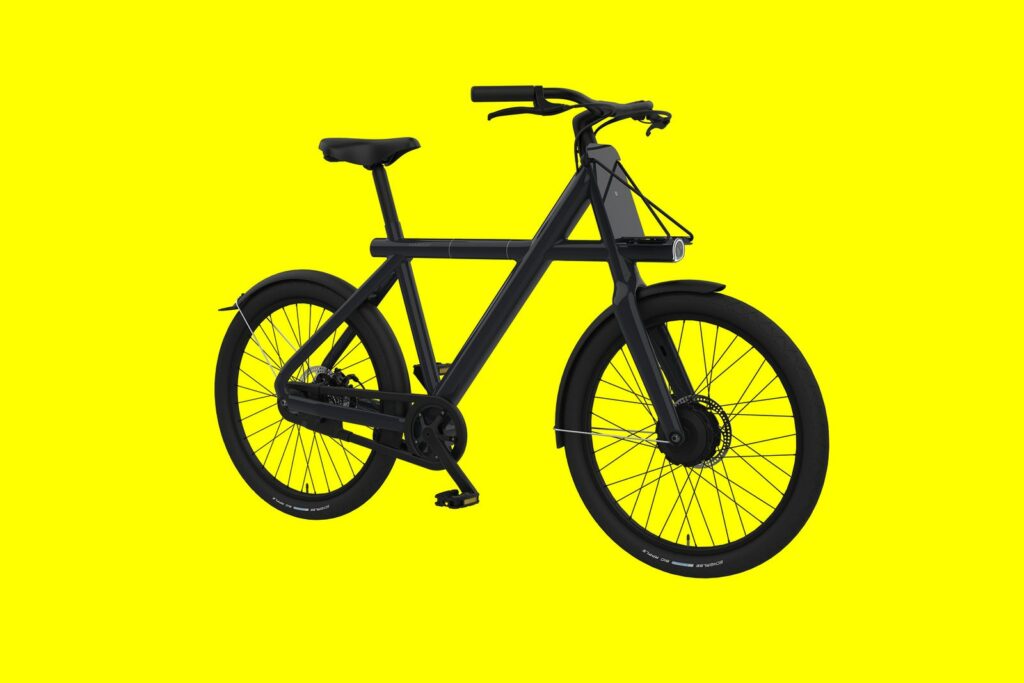
This means you don’t need to be young or super-fit to enjoy getting out and about, with good speeds and longer distances very achievable. And if you want a challenge, you can always switch the assistance off!
Ebikes come ready built to ride away, but an existing machine can be converted.
The three-wheeler challenge
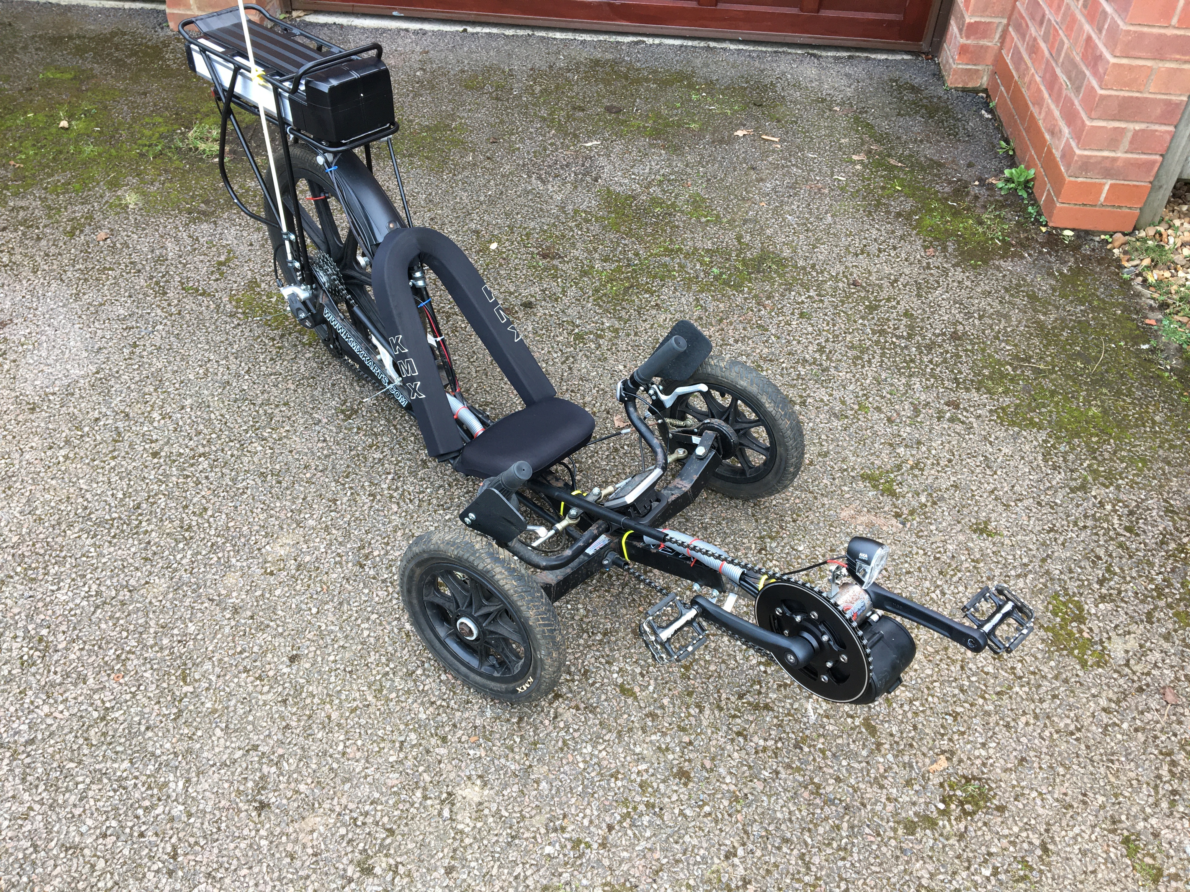
Given the benefits to two-wheeled cycling from going electric, a similar upgrade to an existing 3-wheeled recumbent trike was called for.

In principle, this is ‘simply’ a matter of adding an electric motor and a battery, which is indeed what was done, but there were a few challenges along the way.
Step 1: choosing the electric motor location
The first major decision to make when converting or purchasing any electric cycle is the location of the motor; there are three options: front-wheel, rear-wheel or bottom-bracket mount. For the Trike, with its two small forward wheels, front mounting is not possible. The rear option would require the replacement of the wheel with one with a hub motor, and anyway this can be considered an inferior location given that the motor drive is separate from the rider’s push of the pedals.
Consequently, a bottom-bracket motor was selected, which confusingly on a recumbent trike is not a ‘centre mount’ because it is located at the front, ahead of the front wheel.
Step 2: Motor selection
There are now an expanding number of manufacturers of electric cycle motors, but some of these are only built into new bicycles, and others are prohibitively expensive kits. However, some very affordable Chinese products are available via AliExpress. The selection of the Tongsheng 36V 250W Tsdz2 model from pswpower was made.

Given the restriction in the UK of a maximum speed of 15.5 mph for powered assistance and limit of 250W, this unit is perfectly adequate for the intended task.
Step 3: Bottom Bracket ‘special’ fit
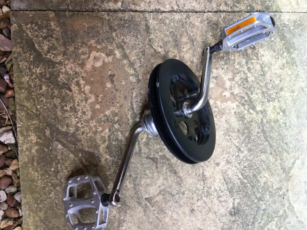
The ‘Bottom Bracket’ is the place on all cycles which enables the pedals to rotate, with bearings facilitating the movements of cranks. However, there are many ‘standards’ of different manufacturers models, so getting a motor to fit in place is not necessarily straight-forward. The existing Trike had what is known as an Ashtabula or ‘American’ one-piece crank’ (OPC) Bottom Bracket, whereby the cranks for the pedals on each side are formed from a single unit and uses a 51.3mm bearing cup pressed into the frame.
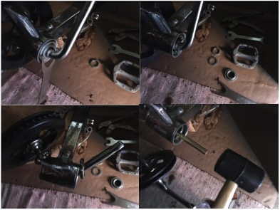
Unscrewing the crank retaining nut was aided by use of a Park Tool HCW-18 spanner. One of the pedals was taken off, the bearings teased out, and the crank fed out. Then a brass drift punch bar helped to hammer out the mounting cups from each side.
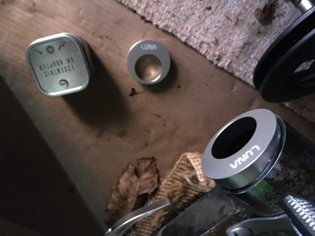
The difficultly then came that the mounting shaft of the Tsdz2 motor is smaller than the bottom bracket diameter, and is also offset. Fortunately, there is a perfect conversion solution to this problem already available, called the Eccentric BB adapter. This converts the Ashtabula empty shell to standard BSA size 34mm diameter (68mm width), but also is asymmetrical mounting which perfectly accommodates the offset motor shaft. This though is somewhat tricky to source; eventually located at Luna Cycle in CA, USA.

Fitting the adapter required careful insertion either side, being a close fit and needing gentle assistance with a mallet, also ensuring that the rotation of two halves lined up.
But once fitted, the motor was slid in and the offset mounting ensured that the shaft located without difficulty or fouling of the frame. The retaining bracket was fitted to the motor and secured with two M5x16 bolts, and then the M33 retaining nut was screwed into place and tightened using the special ring spanner tool supplied with the motor.

The fixing block was then attached with an M8x40 bolt, and the motor assembly secured in place using the bridge-plate, needed to prevent the possibility of the motor rotating in the crank when being powered in operation.
Step 3: Cranks and pedals
The cranks then fitted to the motor spindles either side. The supplied 170mm long parts were too long for the recumbent machine, being designed for a standard bicycle, and hence a pair of 152mm cranks were sourced, which matched the length of the original ones, which being an all-in-one unit couldn’t be reused. Neither could the pedals, which were a different screw size, and so standard gauge replacements were fitted.
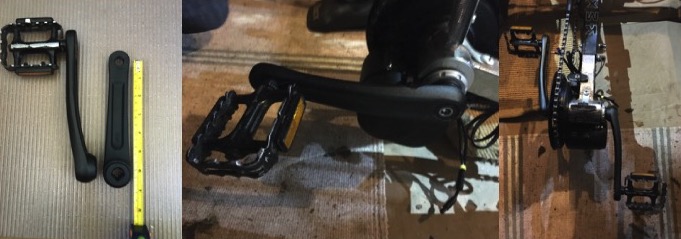
These feature a reverse thread for the left-hand side, which therefore was secured by anti-clockwise rotation, whilst the right hand naturally secures clockwise.
Step 4: Battery fitment
Next came the addition of the 36V 13Ah Lithium-Ion power source. There are various types that can be used on standard bicycles, including down-tube or top-tube units, and bottle-type, but the recumbent trike doesn’t have space for any of these. Instead, it was necessary to add a rear carrier, mounting over the rear wheel, to house a rack mounting battery purchased through eBay from 167-tradeworld-uk. This wasn’t a completely straight-forward fit, as first the rear axle position had to be slightly centralised to accommodate the brackets, and then 16mm pipe clips were needed be added to the frame behind the seat for attaching the front stays to secure the rack. This ensured that the rack didn’t slide or rotate forwards or backwards in use with the weight of the battery.
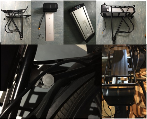
With the rack secured, the purpose-built battery housing was screwed in place on the lower row of the carrier. Then the battery was slid into place and secured with its key lock. Charging of the battery can be made in situ, though it can also be removed for this purpose. This was fully charged using the dedicated mains / 36V power supply adapter.
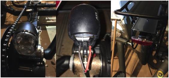
Step 5: Display mounting
An important part of the electric conversion system is the incorporation of a display, which connects the power and controls the cycling assistance, whilst also providing useful data such as speed, distance and charge remaining.
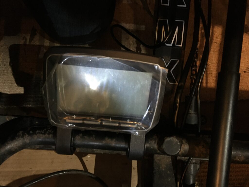
For this project, a VLCD5 display was chosen, ideal for the purpose. Due the limited room and mounting options, given that there are no high up handlebars or top tube on the recumbent trike, the display was mounted centrally on the low steering crossbar. This was secured via the two horizontal attachment loops, thus in use being positioned between the rider’s legs.

The optional remote button control was additionally located on the left handle grip, though this was subsequently found to be of no practical use in operation.
Step 6: Wiring up
With all the main components in place, all that was left was to make the various wiring connections, starting with linking the battery to the motor. The battery came with an XT-60 socket, whereas the motor has 4mm bullet connectors. Also, due to the forward mounting location of the motor, a cable of approximately 1m was needed to link the parts, converting the connection types in the process.
Next, the speed sensor was fitted to the left-hand rear wheel stay and accompanying magnet to the spokes, by means of cable ties. This is the means by which the control unit calculates and therefore displays the speed and distance travelled.

The attached cable contains a splitter which is used to connect to both the display unit and also optional front and rear lights. Chosen for this purpose was an AXA Echo 15 switch for the front, and a Lynx rack mounting e-bike red LED for the rear, both of which fortunately accepted the 2.8mm mini spade connectors on the wiring harness.
This combination cable was again too short to link the display with the sensor, so an additional 1m speed sensor extension N58B cable was added, this having the required 6-pin male/female connectors to plug into the splitter cable and the corresponding motor connection.
Step 7: Powering up and Configuring
The final step was to switch on the battery using the key and control panel with a press of the power button, and then set about configuring the system parameters.

The wheel size was set to 20 inches, and the distance measurement to miles. The i-button on the display module cycles the modes from ODO (total distance), TRIP, AVG (speed) and TIME. The +/- buttons increase/decrease the selected assistance level from ECO (minimum), TOUR, SPEED to TURBO (maximum).
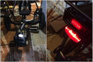
The front and rear lights can be switched on and off with a short press of the power button. The rear battery light can be additionally manually switched on.
A long press of the power button switches the display off.
Finishing up and testing
To finalise the build, some cable sheaths were added to tidy up the wiring, and cable ties secured all the leads. The original flag (useful for visibility for such a low-down vehicle) was cable tied in position against the rear rack.

The eTrike frame was adjusted for the right seating position. Now was time for a test ride!

The completed machine performed perfectly well, providing, as most electric cycles do, assistance from a stationary start up to the legal maximum of 15.5 mph. Pedalling effort is still required by the rider, but the effect is to ‘flatten’ hills (and reducing the need for gear changes), making the experience less strenuous and more enjoyable, maintaining a greater average speed and achieving longer ride distances.
In conclusion, the eTrike conversion was relatively straight-forward, once all the necessary component parts had been identified and sourced. Since recumbent trikes are a somewhat specialised form of cycle, and tend not to be alike, then it is to be expected that a degree of customisation is required to achieve the build of a suitable electric conversion.
Your transformation projects
@YellowsBestLtd assists customers in developing their business and improving and maintaining their infrastructure. Should you have any requirements or plans, please get in touch to discuss how we may be of assistance.