Although the installation of fibre broadband services have been rolling out across the UK for some time now, there still seems much confusion relating to the various services on offer.
@YellowsBestLtd has been receiving ‘Fibre To The Premises’ (FTTP – sometimes referred to as ‘Fibre To The Home’ FTTH) from @Gigaclear since our formation in 2015. We are therefore able to provide this brief summary of our experiences and comparison of the types possible and their capabilities:
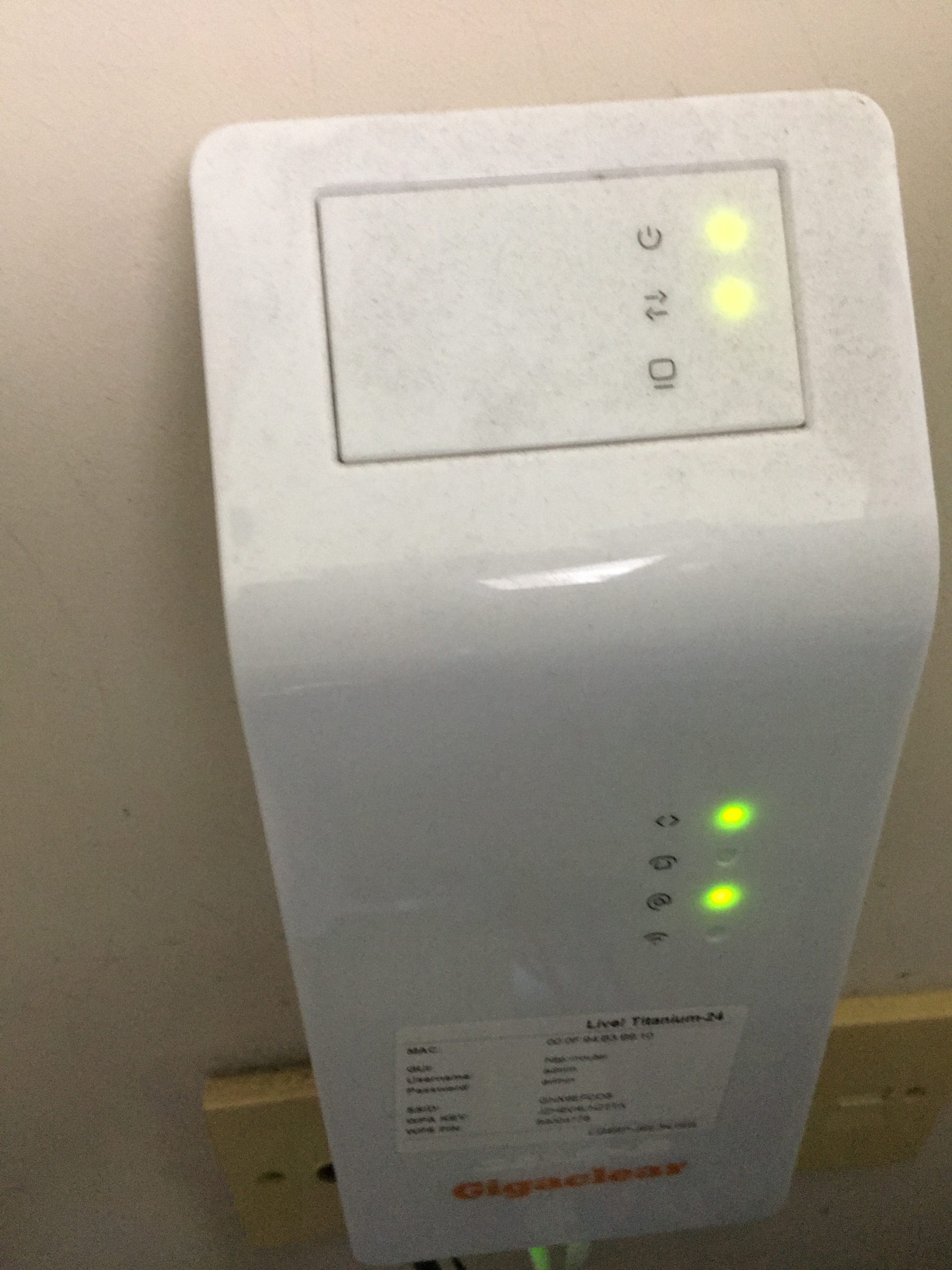
Full Fibre (FTTP) – fibre runs directly to the office or house, giving the fastest and most reliable speeds. This is what we had installed by Gigaclear; a dedicated fibre line into a fibre modem which can be directly connected to using ethernet cable or via a wifi router.
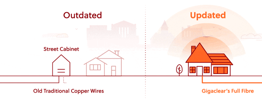
Part Fibre or ‘Fibre to the Cabinet’ (FTTC) – fibre runs to the neighbourhood cabinet, and then data runs over copper lines into the building. The transmission speed and bandwidth is therefore reduced in comparison to Full Fibre. This is the type of on offer to many consumers where the local telephony provider is not able to rollout fibre replacement for the ‘last mile’ of copper connection.
Copper or non-fibre – the traditional, existing telephone lines are used to provide the broadband service. This naturally provides the slowest speed and least data bandwidth. Many communities still rely on this as the only means of internet connection, since no fibre broadband deployment has been made.
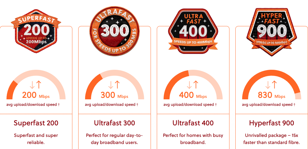
The net result is that with Full Fibre, it is possible to receive previously unheard of speeds. Indeed the maximum service on offer is so fast, it outstrips the requirements of most homes and businesses. It is therefore typical that a reduced service is selected purely for cost-saving purposes.
Our own experiences have found that the Ultrafast 300 service from Gigaclear to be more than adequate for our needs. This is a screen shot of an actual speed test of the service we are being provided with:
In many cases the ‘full fibre’ service we have chosen, approximately a third the speed of the maximum possible, is still at least 10x faster than part or no fibre services. Not only is it faster, it provides a very stable connection less prone to interference and service outages. Thought due to network backhauling connections, is not unknown for interruptions to be possible; fortunately these are relatively rare.
The main difficulty for most businesses and homes remains the lack of universal provision. Whereas we have no reservations in recommending Gigaclear’s full-fibre service, we recognise this is not available everywhere. It is just fortunate for us that rural communities like ours was prioritised in their initial service rollout.
@YellowsBestLtd our mission is in “Keeping Customers Operational”. We’re always keen to enhance our range of #business services, increase the #enterprise infrastructure we support and expand our mix of #sustainable solutions we offer for supply and maintenance of new and legacy #technologies and products for our customers.
Please get in touch to help us understand your management services or solutions requirements, whether you’re implementing new systems or maintaining existing infrastructure networks to serve your operational business needs.
Here is a recent problem which would appear to be quite common. The end of the connector on a lightning cable was stuck inside the charging / accessory port. This worryingly appears to be a frequent occurrence resulting from the use of cheap, unbranded cables where the tip of the connector can break off, forming a staple-shaped piece, jamming itself into the iPhone or iPad. The result is that it is impossible to charge the device, unless the broken connector lead is retained, as it is the only one now small enough to fit into the accessory port.
This problem can render the expensive phone or tablet useless. For older out-of-warranty products it is potentially not worth a repair investigation and even with newer devices this may be classified as ‘accidental damage’, requiring extended insurance cover to avoid a significant resolution cost.
Happily, it may be possible to address the problem using the following simple technique:
Use a ultra-small, precision screwdriver. It needs to be small enough to easily fit inside the accessory port and be able to be levered across it’s width, whilst being sturdy enough not to bend or break.
Insert into the device’s accessory port, and position sideways across the width of the opening, such that the end of the tool is pressing on the inside of the port about half-way in / up.
Then, with an outwards ‘levering’ action, pull the broken connector piece out of the port.
If fortunate, this will remove the obstruction and return the device to an operational state. Naturally, success is not certain and there is the risk of causing further damage. Hence, particularly with newer devices, if you are not confident in your abilities then best to consult an electronics specialist or seek professional assistance from an approved repair centre.
The lesson from this experience is to purchase good quality, branded accessory leads and dispose of any cables where the connector shows signs of wear.
Maintenance of new and legacy systems
@Yellowsbestltd our mission is “Keeping Customers Operational”, by assisting with with the repair of parts for infrastructure systems. These are typically established, long-standing and therefore proven and fit-for-purpose. It makes sense to maintain and extend the life of these systems, as wholesale replacements will be costly and disruptive. This is particularly applicable when the service requirements have not changed, so functionality upgrades are not necessary.
Wewould be keen to hear from you should you have any repairs requirements. Please get in touch to let us know how we can help. By example, there follows a list of a few recent requests we have been able to assist with. We look forward to hearing from you with any feedback you may have.
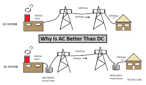
Following on from our recent post on our Solar Power System – On Grid Project, the observation has been made that it’s rather inefficient to generate power as DC electricity, and convert it to a higher AC voltage, before converting it back again to DC to suit many consumer applications.
Voltage multiple conversion
The issue of use of AC or DC is not a new one. Famously, in 1893, Thomas Edison who promoted the generation and use of DC ‘lost’ the battle to George Westinghouse who gained acceptance for the generation of AC at the Chicago World’s Fair, since it was more efficient in long-distance transmission.
This has been the situation for more than a century and still applies with generation at remote power stations and transmission at high AC voltage to feed and satisfy local demand. The 240V (in the UK) AC mains electricity that is delivered to a household is perfectly suitable in this form for domestic high power applications i.e. cooker, washing machine, etc. On the other hand, electricity is used for variety of low-voltage DC devices and gadgets e.g. phones, TVs, computers and so on, contain power adapters converting AC to DC and stepping down to typically 12v or 5v USB. Lighting is traditionally AC, but with advancement in LED technology could be of a lower DC voltage.
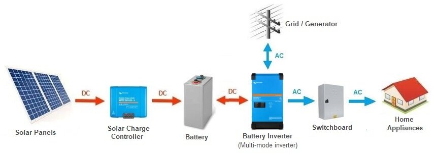
The development of locally generated solar energy changes things somewhat. The generation output is low voltage DC. The majority of this generated electricity is utilised locally. Excess energy can be stored in batteries, which are also low voltage DC. This could be used in this form, but in order for a household to be able to supplement locally generated energy, when the sun doesn’t shine (night time / winter), it still has to be wired to receive AC from the grid-based electricity. Also, to facilitate the export of excess energy (an increasingly valuable benefit of domestic solar power generation), the locally generated electricity must be converted to grid-compatible AC, using an inverter.
It should be the case that houses of the future are designed and built with solar panels on the roof. Indeed, it is now the case they are cheaper that slate, and so the materials and labour charges would be negligible costs if part of the build rather than as an add-on. In which case, the building could be designed with 12V DC and 5V USB supplementary to the 240V AC for mains wiring, feeding appliances directly at the type of voltage they require, eliminating power rectifiers and most voltage converters.
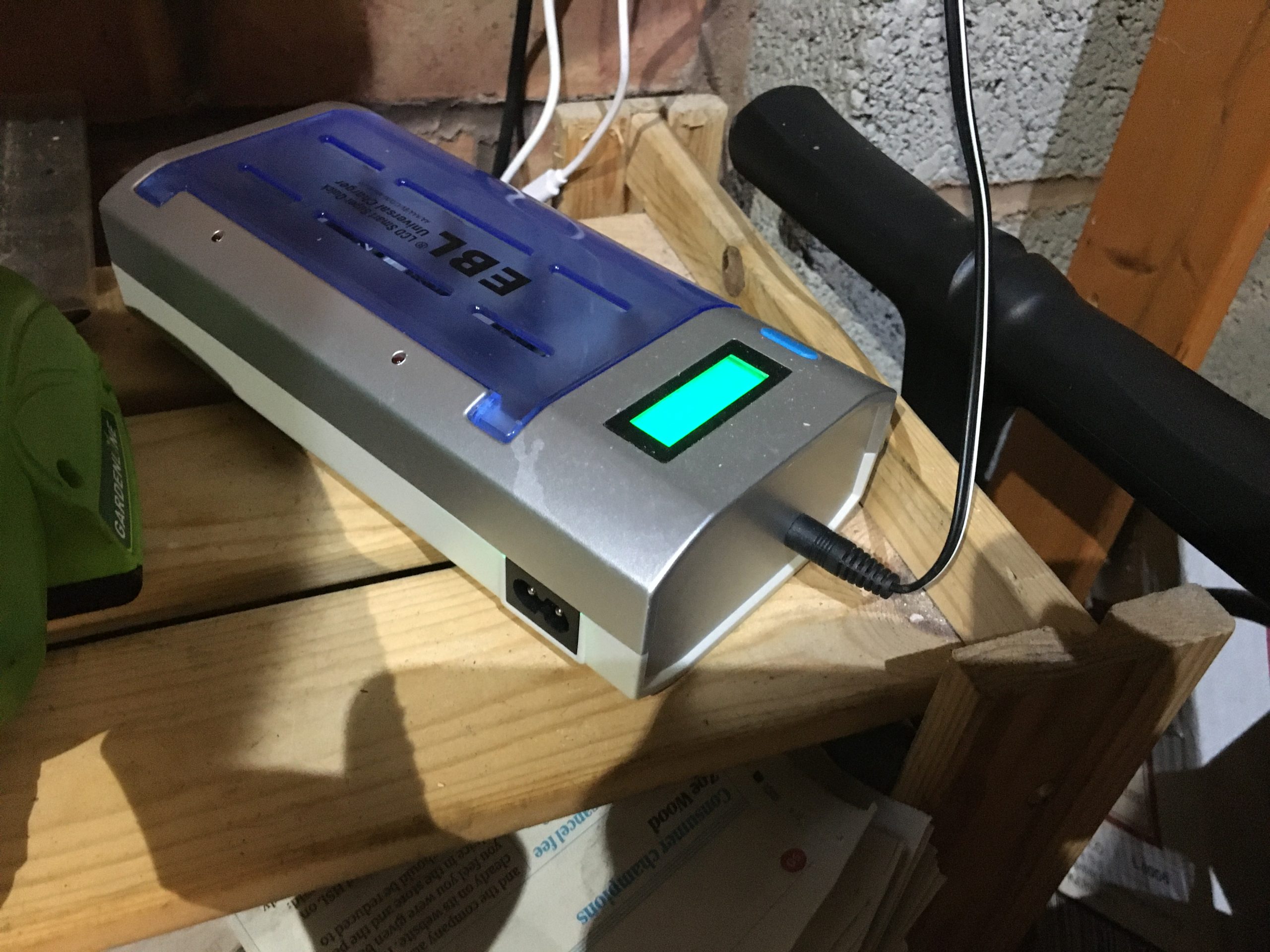
This ‘direct supply’ is already demonstrated in our Solar energy off-grid eBike charger project with the generated supply connected to a AA / AAA / C / D / PP3 battery charger using its 12V DC input (bypassing a 240V AC input, which requires internal conversion). The 12V supply also feeds LED lights without voltage conversion.
Charging batteries from 12V DC Solar Energy
Similarly, the 5V USB outputs of the solar charger controller can charge iPhones and other gadgets.
Solar Charge controller with 5V DC USB sockets
‘Highway to Hell’ – EV charging & V2X
We know that Electric Vehicles (EVs) are going to be increasingly in use and will gradually take over from petrol and diesel engines.
PHEV charging
And so the ability to charge these at home will be increasingly important and convenient. Some cars are already of a Plug-in Hybrid Electric Vehicle (PHEV) type, meaning that they can be charged from a domestic UK 240V AC supply for local use.
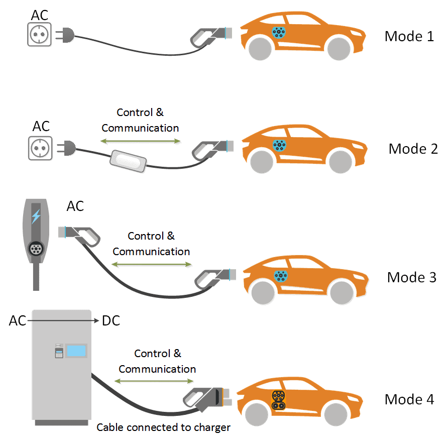
Another key development is the concept of EV batteries being used as supplementary storage for a household, so called ‘Vehicle to Home’ (V2H), ‘Vehicle to Building / Business’ (V2B) or ‘Vehicle to Grid’ (V2G) [collectively V2X indicating bi-directional, as opposed to single direction V1G], charging at low demand and discharging when household usage is greater, or to take advantage of higher export pricing.
V2X Charging types
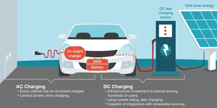
The AC supply is needed to be converted to a DC voltage useable by the car batteries, and similarly the car’s electricity needs converting from DC to AC for household export. There are two ways of achieving this, by having a converter in the charger or the car. But if the premises has its own source of accessible DC power, ideally sourced from locally generated solar energy, then this conversion would be unnecessary.
AC vs DC charging
Another issue is that UK 240V AC is limited to 13A supply from standard household sockets (for most domestic use) providing slow charging at 3kW. A dedicated charging point using a UK Type 2 connection is an improvement with direct connection to the mains consumer unit, providing charging at 3.6kWh from a 16V AC supply or 7.4 KW from a 32V AC supply. Faster charging is possible with 11kW from 32A AC supply or faster still with 22kW from 63A AC supply, but these are more expensive, beyond the available power of many households and require a 3-phase supply.
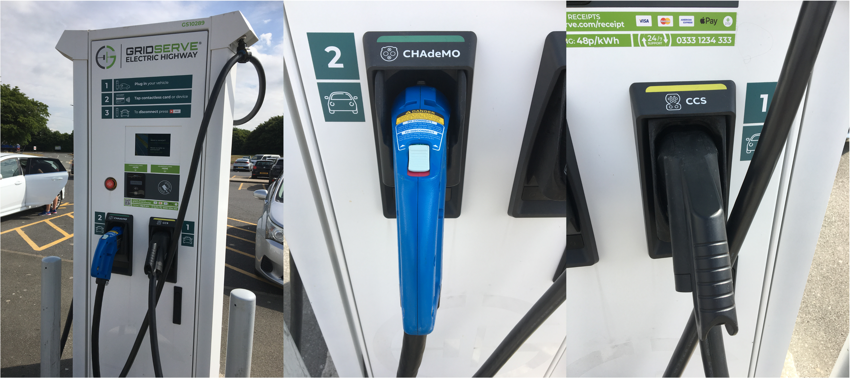
The European Union has specified the Combined Charging System (CCS) standard to permit both AC and DC charging. Much faster and more efficient charging at 100kW and beyond is possible using DC charging, eliminating the conversion in the vehicle. However, this is currently an even more expensive solution and limited to EVs that can accept a compatible DC input. Charging at commercial sites such as motorway service stations offer a variety of standards, including the CCS (Europe), CHAdeMO (Japan), GB/T (China) or Tesla Supercharger (propriety).
EV charging service station offering both CHAdeMO and CCS standards
This conversion and compatibility issue is not confined to motor vehicles. As highlighted in the Solar energy off-grid eBike charger project, conversion using an inverter is necessary from the 12V DC power generated from the Solar Panel and stored in the battery, to 240V AC used by the required charger, which then converts again into 36V DC. The problem is not just related to type and size of voltage, as the lithium batteries used require special adapters to perform the charging correctly. It would be possible to produce these fed from a specialist DC adapter, but such chargers are more difficult (and expensive) to obtain, given that the domestic supplies are generally not available in this form and so consequently the demand for these products is not yet there.
‘Thunderstruck’ – Solar powered cooling (mini project)
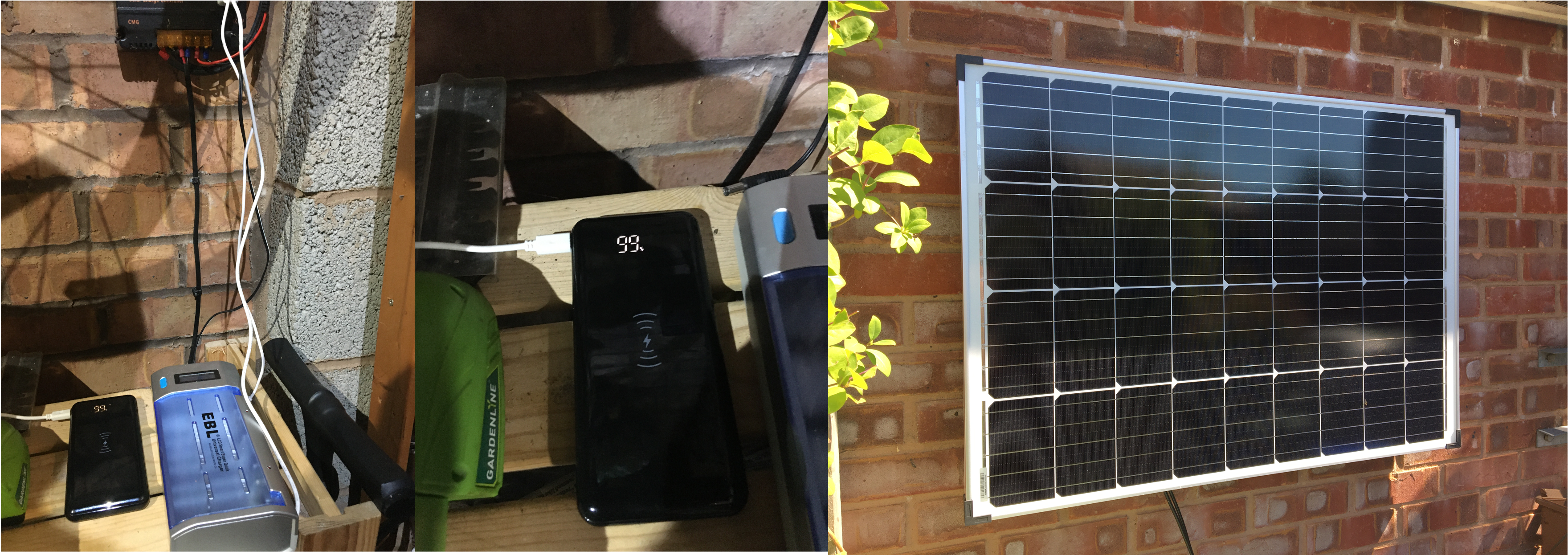
Given the current heat-wave and the likely-hood of more temperature extremes as a result of climate change, coupled with cost-of-energy crises and possible supply shortages, it seemed appropriate to build another solar power project, this time focusing on powering a cooling fan with energy from the sun.
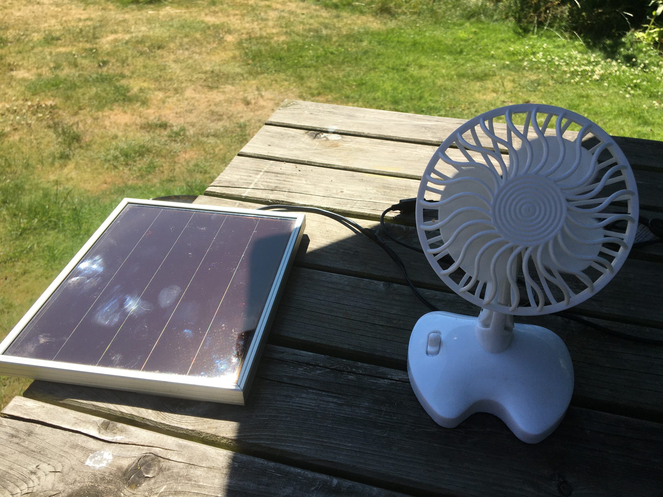
The concept is relatively straight-forward: using solar energy to assist with cooling. When sitting out and the sun is shining and the temperature is too hot, the sensible thing to do is shelter under some shade. But when there is little-to-no breeze, even in the shade it gets too hot to bare. In which case, a simple fan can help. The one selected was an old, cheap USB model, which provides a limited amount of cooling, but doesn’t require much energy to operate. Also chosen was a small, also old, and low-cost 6V solar panel, which provides just enough energy to power a USB device using a suitable conversion lead.
Solar powered fan
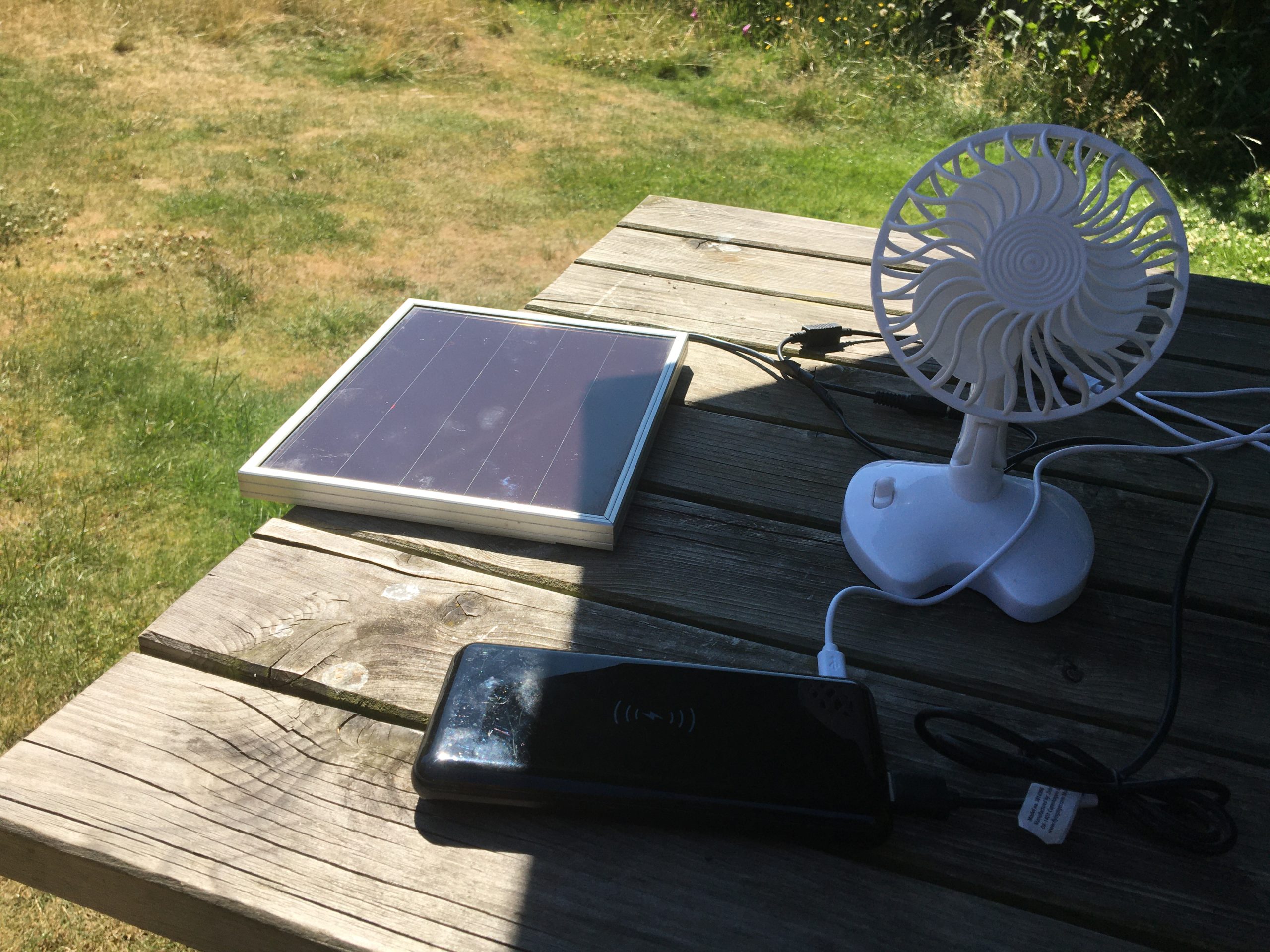
But this isn’t particularly robust since a slight drop in sunshine can stop the set-up working. Hence this has been additionally paired with a battery power bank, which can simultaneously be charged with the solar energy whilst also powering the fan.
Solar powered fan with battery bank
Naturally, the battery pack can be charged separately – ideally powered by locally generated and stored solar energy!
Charging the battery bank from solar energy
‘For those about to Rock’ – the Electric future
Hopefully this has been food for thought into the exciting fast developing world of solar power generation and the electric future. Please get in touch if you have questions, comments or ideas to share.
@YellowsBestLtd our mission is in “Keeping Customers Operational”. We’re always keen to enhance our range of #business services, increase the #enterprise infrastructure we support and expand our mix of #sustainable solutions we offer for supply and maintenance of new and legacy #technologies and products for our customers.
Please help us understand your management services or solutions requirements, whether you’re implementing new systems or maintaining existing infrastructure networks to serve your operational business needs.
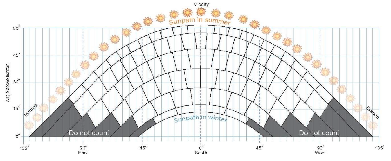
Obtaining low-cost renewable solar energy has always had much appeal, but historically the investment costs has been rather off-putting, especially in the U.K. where it is perceived that the climate doesn’t provide a reliable enough amount of sunshine.
Available sunlight for power generation
However, in recent years a number of things have changed this evaluation. Performance improvements in solar panels and associated power inverters have resulted gains in energy creation, coupled with the availability of modern battery arrays substantial enough to store the energy produced for later reuse. At the same time, shocks to world fuel prices have results in a rapid shorting of the ‘payback period’; once it was considered that a typical household solar installation would take in the order of 25 years to recoup the investments costs. This has tumbled to around an estimated 8 years based on calculations made last year, and taking into account the recent price increases for domestic electricity supply, the period could be approaching 4 years with further shortening likely as energy prices continue to rise. The recent removal of VAT by the UK government on the implementation of solar energy systems is an added boost.
One additional further benefit that has recently arisen is the introduction by some power utility companies, such as Octopus Energy, of ‘agile’ export tariffs, which pay increased amounts at peak demand times. This can be taken advantage of by the use of smart meters, supplying surplus generated or stored energy to the grid at the best times to maximise revenue, offsetting the purchase of electricity from the grid at other times.
Given that the future is anticipated to require increasing use of electricity to provide power for EV cars and hybrid vehicles, generating your own electricity makes increasing sense.
Overview of our implemented system
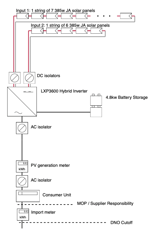
Solar Power System overview
Given the now obvious benefits of a solar energy, we have acted accordingly and implemented a system, which has the following component parts:
13x 385W JA Solar Monocrystalline Panels with PERC technology, limited by the available roof space, but sufficient for energy needs.
Alumero Mounting accessories & Tigo Optimisers to enhance performance when part of the solar array is shaded.
Luxpower Hybrid Auto Inverter, 16A single phase, to convert the generated 12V DC electricity to 240V AC for household consumption or export.
4.8 kW Aoboet Uhome battery storage array to store excess energy for later use.
AC and DC isolators to connect the component system parts.
Generation meter to measure energy production.
Wifi Monitoring portal for displaying instantaneous and historical performance.
The calculated annual yield for this system is 3,679kWh, which should be enough to fulfil the household’s electricity needs, estimated at 3,207kWh based on previous usage.
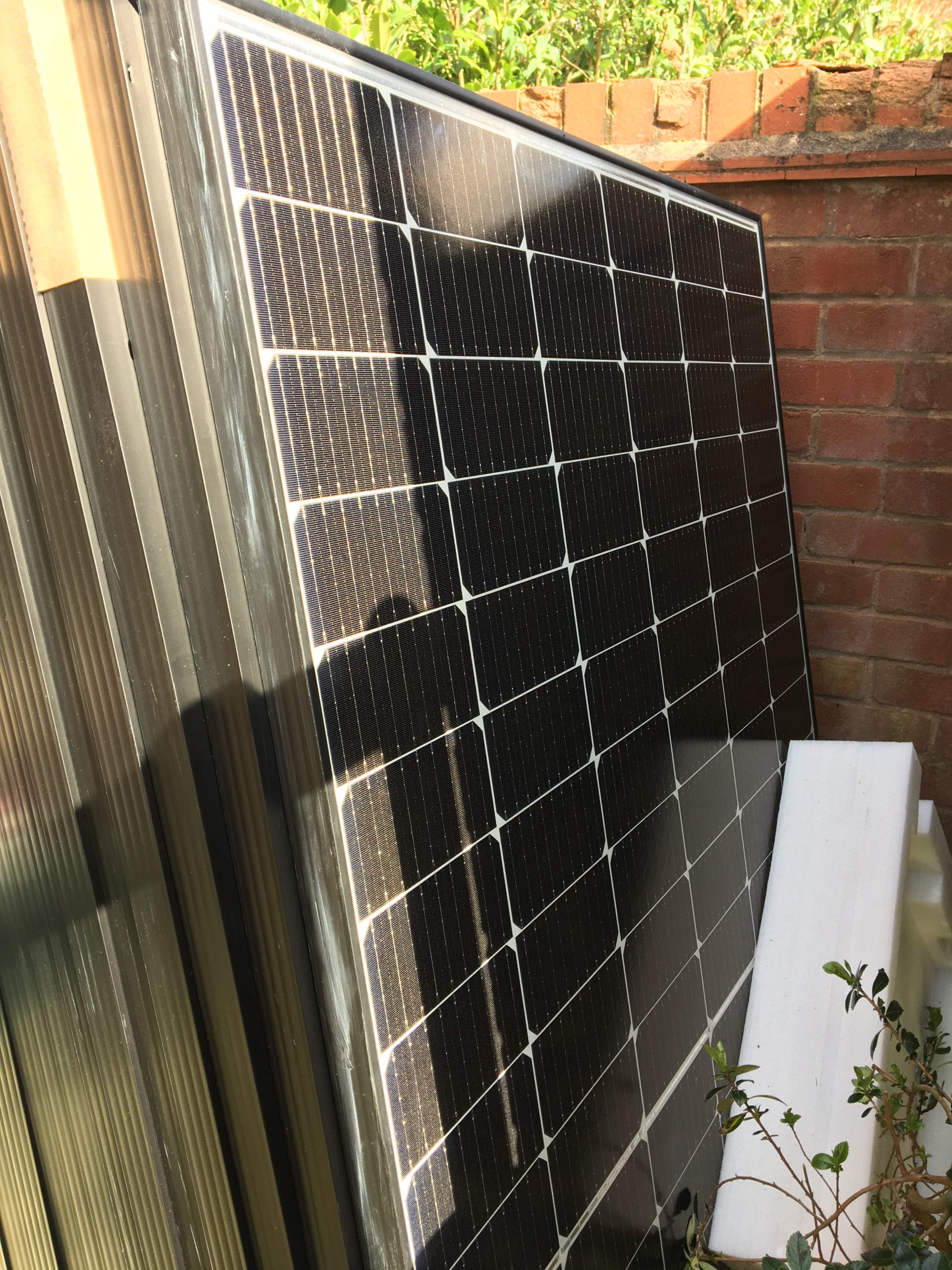
Solar Panels – the ‘heart’
Monocrystalline Solar panels
Key to the collection of energy from the sun are naturally the solar panels. These vary in size, and technology is improving continuously, so the latest available are more efficient than previous generations.
Those selected for this project were 13 x 385W JA Solar Monocrystalline Panels with latest PERC (Passivated Emitter and Rear Cell) technology. Monocrystalline are more expensive but more efficient, with a longer lifespan than other types available. PERC technology improves light capture near the rear surface, optimising electrons flow and thereby achieving higher efficiencies.
Solar Panels installed on the Roof
The amount produced by a solar array naturally depends on sunlight hours and will be much lower with poor weather or as daylight reduces, whilst household electricity demand also varies during the day.
The ultimate aim of using solar power is to reduce as far as practically possible the need to source energy from the grid. Consequently, a larger array of modules than those just to meet the typical usage amount is needed to ensure adequate production whatever the weather, with the excess being stored or exported.
Mounting fixtures
Optimisers
Alumero mounting kits were used for fixing the solar panels to the property roof, together with Tigo optimisers which maximise the generation from each panel. Without such optimisation, the power output from all solar modules can be reduced when some of the array is in shade.
DC Isolators
DC isolators connect two ‘strings’ of series connected panels to the Hybrid Inverter.
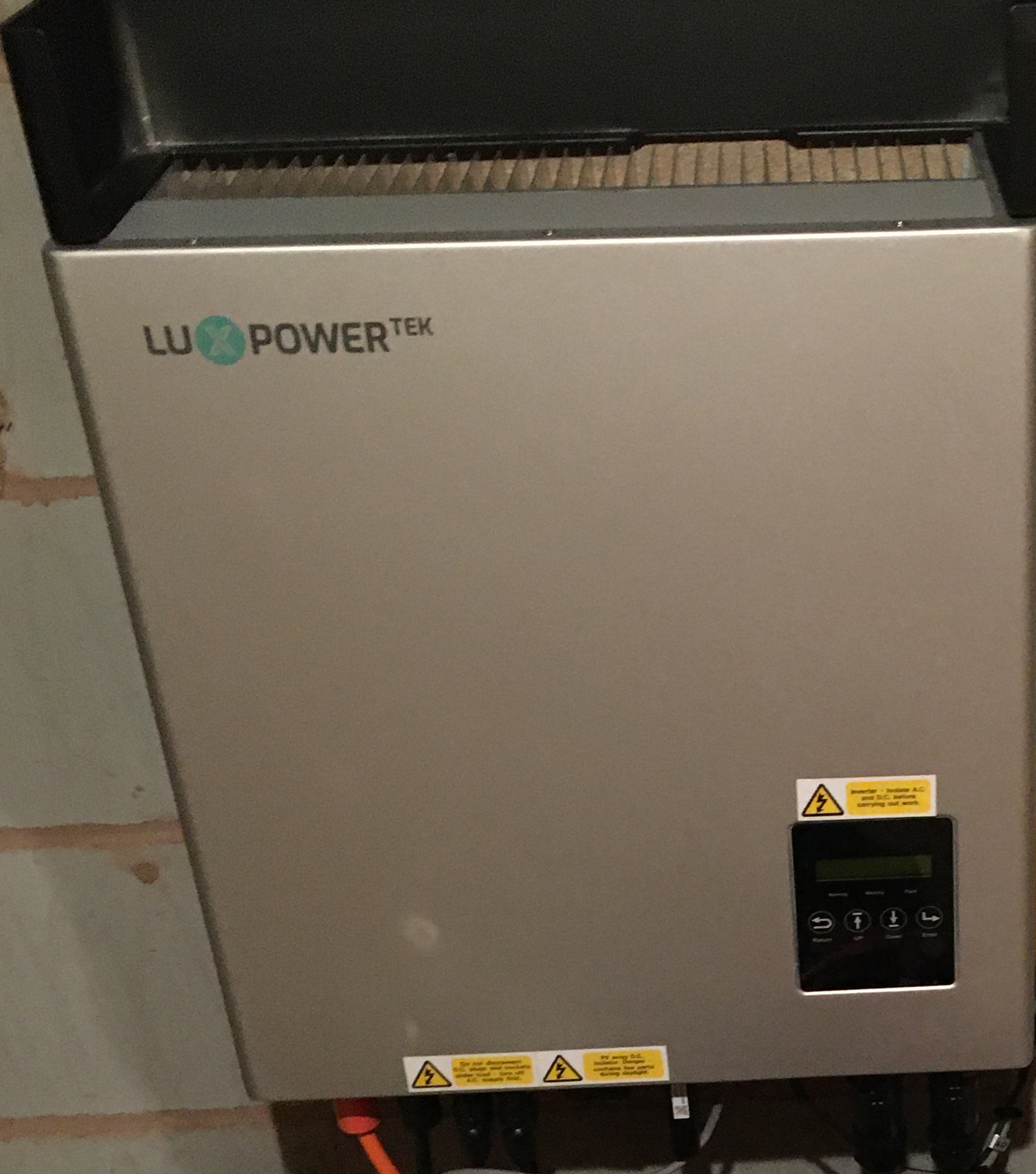
Hybrid Inverter – ‘the brains’
In order for the system to be truly useful, power conversion and energy management functions are needed, to ensure a seamless and uninterrupted supply of electricity from the available sources i.e. an appropriate mix of the local generation, storage and grid supply. Chosen for this installation was a Lux Hybrid Automated 16 Amp single phase inverter.
Inverter
The Hybrid Inverter ensures that when solar energy is available i.e. during daylight hours, this is firstly routed to provide for domestic consumption, and then used to charge the battery storage (as required, if not full). Any additional energy is exported to the external grid. When there is not enough energy generation from the solar array, the hybrid inverter routes the energy storage to the household, and when this is depleted, electricity is imported from the grid in the usual way. Critically, where to source electricity from is completely seamless such that the domestic consumption is never interrupted and the household is unaware of these ‘decisions’ being made.
It’s the inverter’s job to take the DC electricity produced by the solar panels and turn it into 240V AC electricity for household use. It’s a sad fact that many domestic appliances then take this 240V AC and convert it back to DC and lower voltages like 12V and 5V; this double conversion adding theoretical inefficiencies. But this is simpler to implement than rewiring the entire building and trying to then integrate with power to and from the grid.
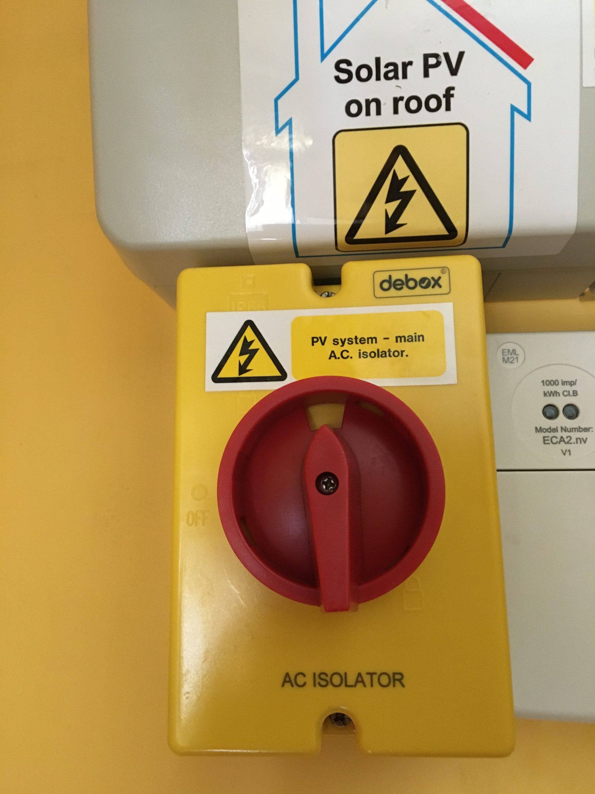
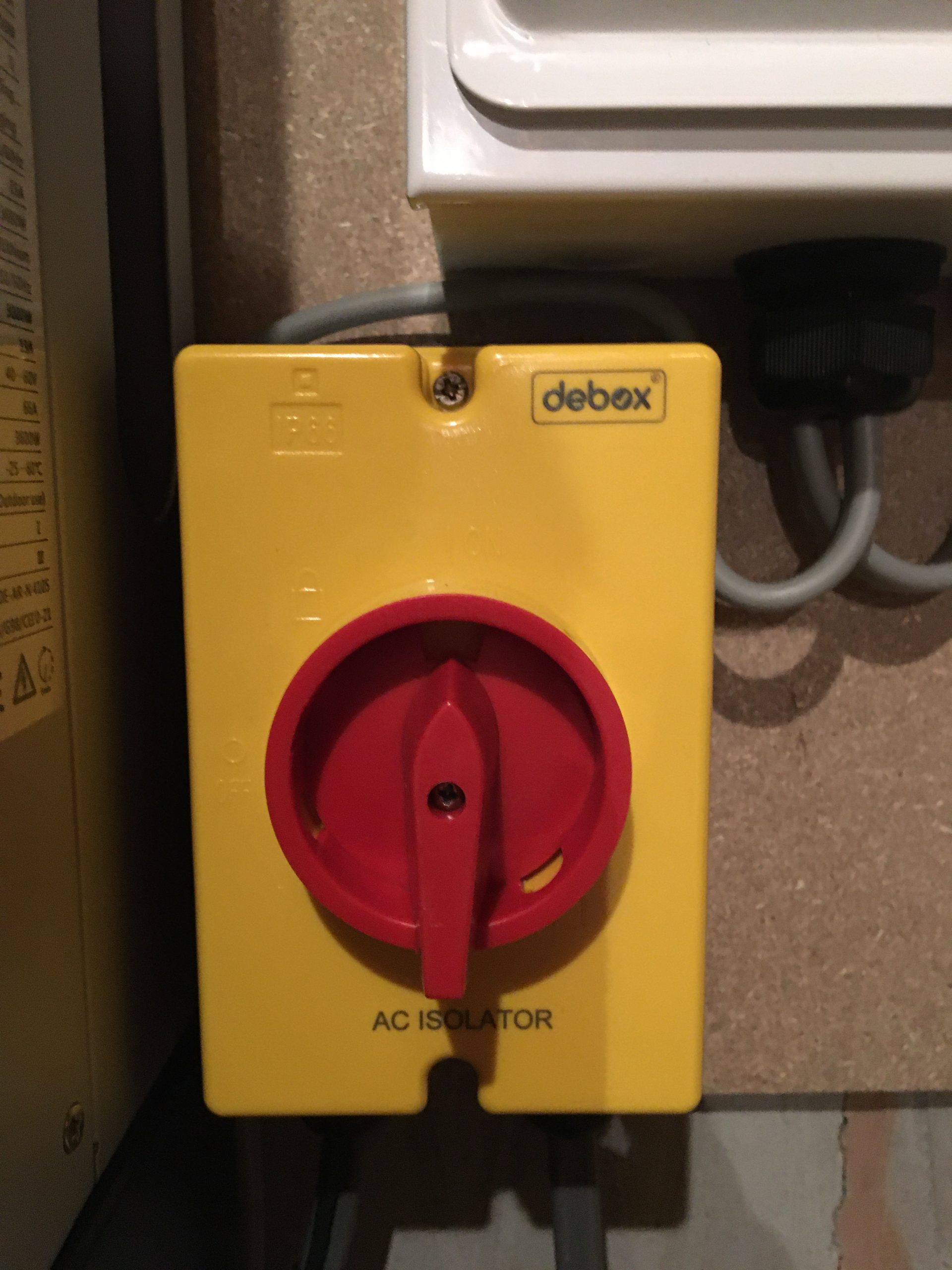
AC Isolator
AC Isolator
AC Isolators connect the Inverter’s output to the household electricity supply.
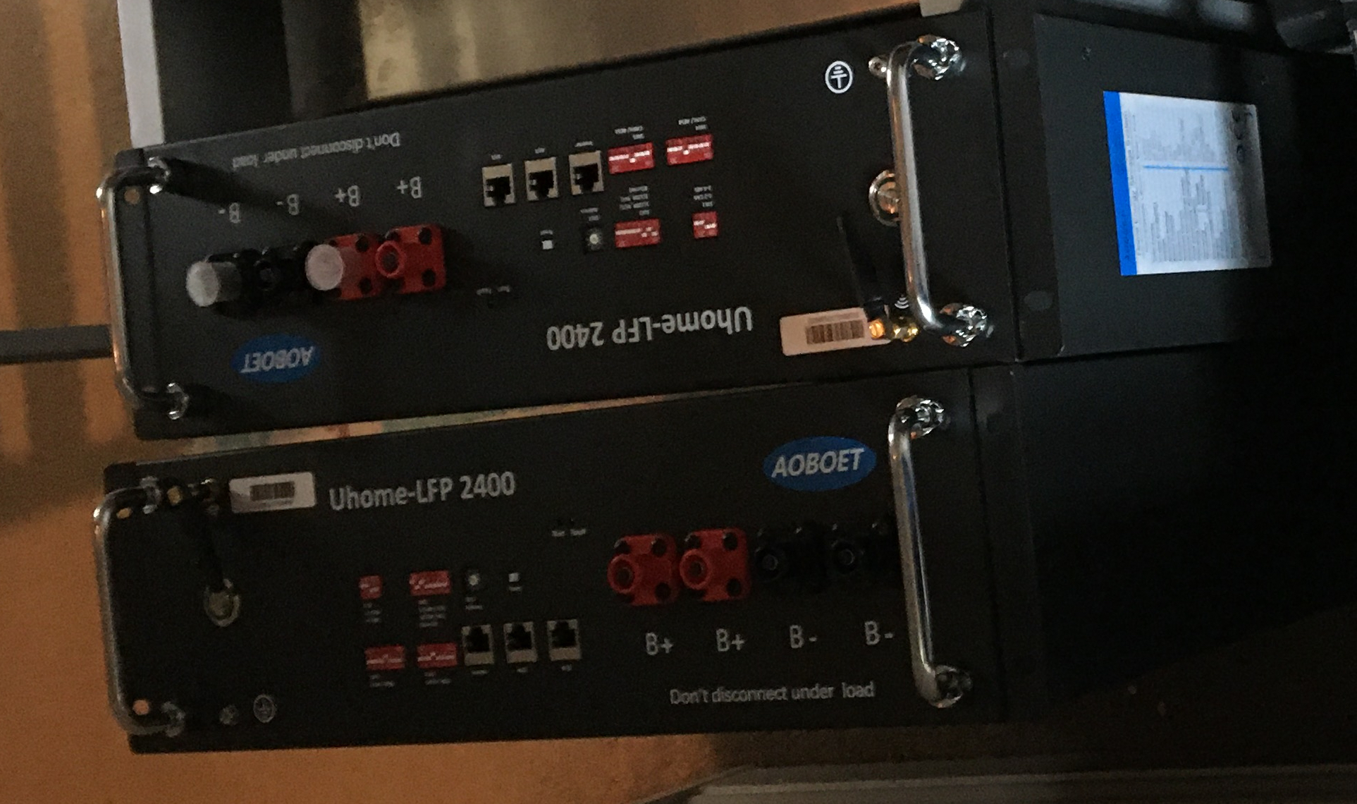
Batteries – ‘the memory’
Quite literally, ‘saving for a rainy day’ is the function of the batteries, which add to the capability and capacity of solar power generation. They are effectively ‘optional’ since the system can be run without them. But since there is a huge natural variation between maximum sunlight and night-time, it makes sense to capture excess energy at peak times, and use this when sunlight is not available or sufficient.
Chosen for this project were 2x Aoboet Uhome-LFP 2400 providing 4.8kW of storage capacity.
Batteries
At the beginning of a day, the batteries are naturally somewhat depleted, and therefore excess solar energy is initially used to charge them. Once full, they remain ‘on standby’ until later when generation is unable to fulfil the immediate electricity needs, in which case they start discharging their stored energy. Ideally, they will not become completely depleted over the course of the day and night, so that energy is not needed to be imported from the grid.
Grid – import / export
Electricity from the grid is the “insurance” for times when the solar energy is not able to fulfil demand. Naturally, this is likely to be due to a lack of winter daylight hours and/or poor weather, which of course has to be paid for.
Generation Meter
But at other times, there will be an excess of energy that can be exported to earn back some of these costs. A Generation Meter as part of the solar energy system enables this export of electricity.
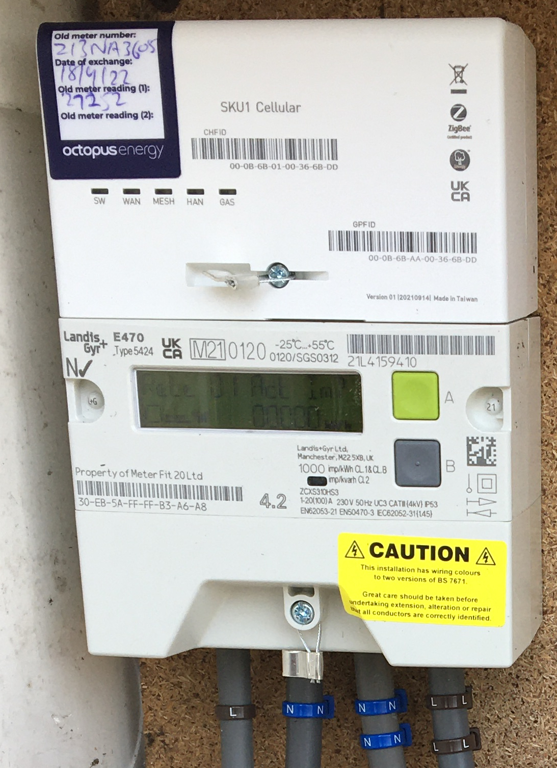
Smart Meter
WiFi Monitor
The bi-directional energy flow is measured with a ‘smart’ meter using a suitable import / export tariff from the Utility company, such as the Octopus with their Agile tariff, and displayed on an associated WiFi monitor.
As to be expected, the amount paid by the Utility for kWh export is considerably less than that charged for import, so it’s worth making best use of the generated and stored energy as much as possible, like running appliances when the sun shines!
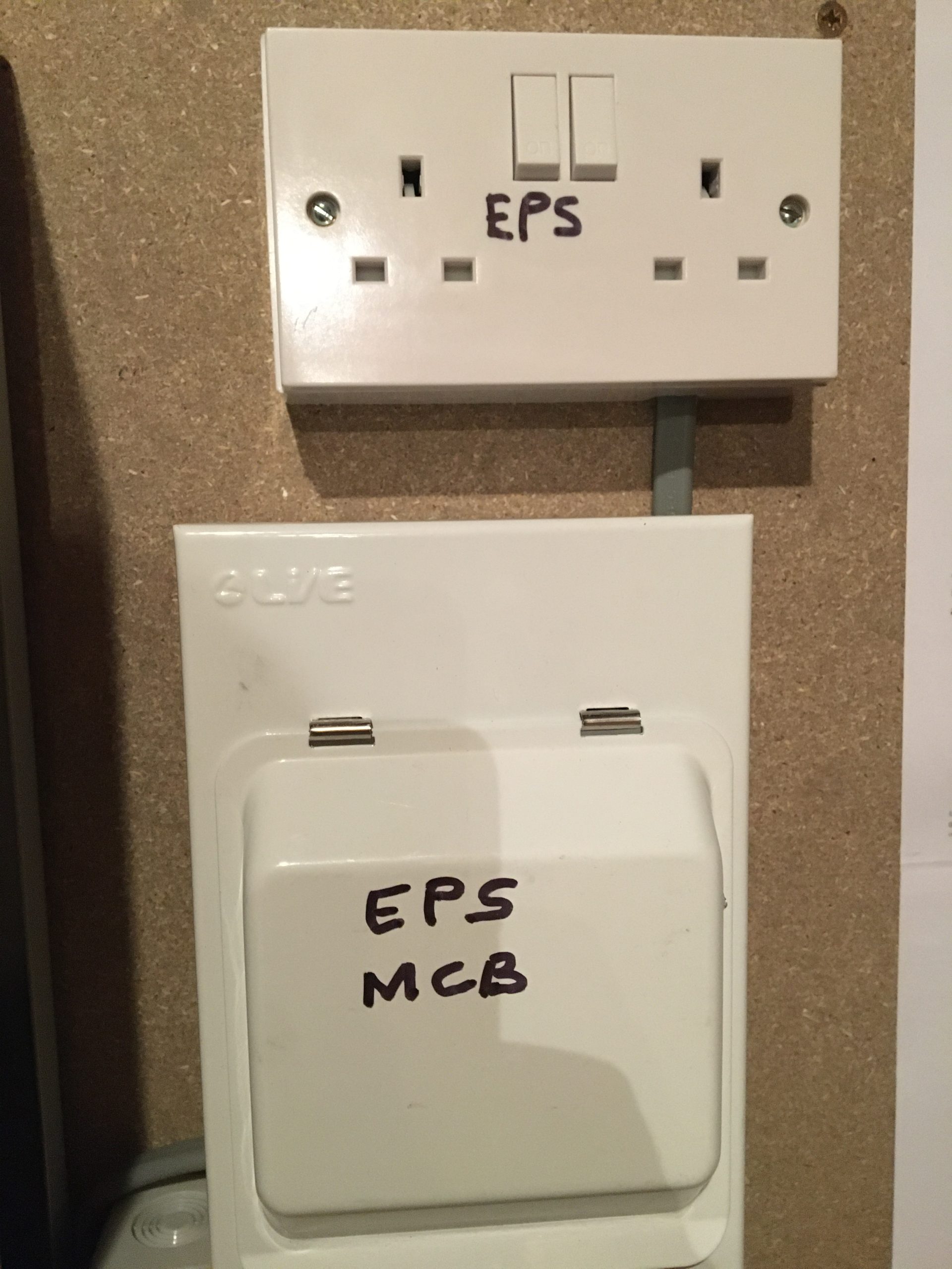
EPS socket
An EPS (Emergency Power Supply) socket was additionally included in this project. Though optional, it was chosen for providing ‘backup power’ from the solar energy system in the event of a power outage from the grid supply. It is standard practice in such an event to shut off the export to the grid from solar energy systems to avoid difficulties whilst restoration work is in progress. But during such a period, the household can make use of the generated and stored local energy, for a limited time and restricted to a maximum of 13A. Avoiding excessive consumption, it should be possible to maintain a local supply for 12 hours, assuming a fully charged battery array.
MCS Certificate
To complete the project to become an ‘energy generator’ (as well as satisfying own consumption needs), an MCS (Microgeneration Certificate Scheme) certificate is issued, together with receiving acceptance documentation from the DNO (District Network Operative). This then allows the establishment of the export tariff with the Utility provider so that payments for excess energy exported will be made.
Operating performance
A WiFi Portal provides the householder with an overview of the current operation of the solar energy system, displaying instantaneous status and historical energy performance for tracking generation yield and import / energy export.
WiFi Portal
Initially, it can be reported that average energy yield is around 0.86kWh, ranging between a typical peak of 2-4kW during the day and zero at night, compared with average consumption of approximately 0.35kWh, with the excess charging the batteries in the morning and exporting to the grid during the rest of the day. During the night, the consumption is met from the battery storage, with the batteries depleted to around 11% by the next day. It is noted that even during relatively cloudy days, at least around 10% of the 5kWh maximum power is generated, enough to at least meet the immediate consumption needs and even provide some battery replenishment.
A complete picture of the operating performance of the solar energy system will be known after a full year, taking into account the peak of summer and the shortest winter daylight period. Rising costs of electricity will also impact on the longer-term cost savings anticipated.
Conclusions
Hopefully this ‘project description’ is of interest and perhaps of use to anyone contemplating installing a Solar Energy system at their home or office premises. Please feel free to get in touch if you would like us to provide consultancy advice (on a no-obligation FOC basis) leading to a quotation for establishing your own system, or just to gain an in-depth appraisal and more information from our first-hand experience of implementing a Solar Energy system.
System Schematic
Our summary of conclusions at this stage having now implemented a system are:
Solar energy collection has developed rapidly in recent years, particularly now that home energy storage is practical enough to capture excess energy during peak daylight and release it for use during the night or whenever demand exceeds generation.
Although such systems are still a significant investment, given the recent escalation in energy costs, the ‘break-even’ point has reduced dramactically and the trend is for energy costs to continue to rise thereby making the payback period increasingly shorter.
An attractive feature is the notion of being paid to supply energy to the grid, though it should be noted that currently at best this is 7.5p per kWh, so unlikely to be a significant revenue source. But it does mean that energy bills over the longer term will be vanishingly small.
The contribution to the nation’s renewable energy mix helps in a small way to aid the drive to reduced carbon emissions and tackle climate change.
Naturally, a suitable oriented roof or land space for solar panel installation is required, as well as a location for housing the inverter and batteries (loft space is ideal). Plus, it should be noted that a PV cable needs to be installed (most likely running down the outside wall of the building) to link the inverter to the consumer unit.
Should power cuts from the grid occur in the future, the solar energy system is capable (thanks to the EPS socket) of providing power for a limited period to maintain household electricity use.
With the increasing use of electric cars (all new will need to be at least hybrid by 2030), being able to source local renewable energy will make increasing sense.
@YellowsBestLtd our mission is in “Keeping Customers Operational”. We’re always keen to enhance our range of #business services, increase the #enterprise infrastructure we support and expand our mix of #sustainable solutions we offer for supply and maintenance of new and legacy #technologies and products for our customers.
Please help us understand what would be of interest to you by getting in touch to discuss your management services or solutions requirements, whether you’re implementing new systems or maintaining existing infrastructure networks to serve your operational business needs. We look forward to hearing from you.
From the beginning of April 2020, all UK VAT-registered businesses will need to keep digital records of all transactions, and then submit VAT returns electronic using compatible software.
Whereas many businesses have already started using Making Tax Digital (MTD), the new deadline means that all businesses of any size that are VAT registered will need to comply.
Signing Up to MTD by the next VAT period due
The new electronic service replaces the ‘manual’ VAT return for businesses on their next submission after the 1st April start date, which remains at the same quarterly interval. So (for example) if the business’s current VAT period is February to April, then this can be completed in the usual way when due in May. But the following VAT period of May to July will require a digital submission in August (and thereafter). Signing up to MTD needs to be made at least 7 days before the date the first MTD return is due. It’s important however not to sign up less than 5 days after the last non-MTD return, to avoid duplication of payments.
Signing up is accomplished via the MTD GOV.UK website, requiring a Government Gateway ID with business and VAT registration information.
Obtaining and using compatible software
Various providers of accounting software are available to both record digital transactions and make the electronic VAT submissions. This also includes using spreadsheets, though in that case bridging software will be needed to make the submission.
A top tip for NatWest Bank business customers is that they will provide the MTB compliant accounting software FreeAgent at no cost.
Assisting with your business requirements
@YellowsBestLtd would be interested to receive feedback on your transition to MTD and any other business transformation challenges you are facing. If appropriate, there may be areas of your business development or operations that we can support with consultancy services e.g. sales and marketing assistance. Please get in touch to discuss how we can be of help.
Information Technology (IT) is a familiar concept to most modern office workplaces encompassing the products and networks providing data-centric computing, supporting various business functions such as finance, personnel, management and administration. This has grown to being fundamental to corporations large and small, and continues to rapidly develop in scale and capability.
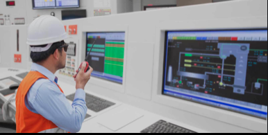
Operational Technology (OT)
By contrast, Operational Technology (OT) is understood by utilities, transport, manufacturing and other industrial sectors, as encompassing an array of systems engineering, event monitoring and process control to facilitate operations. Historically, the technologies and products used to implement the required infrastructure have been bespoke and separate from other corporate systems.
The growth of standardisation
With the explosion of computing devices, the internet and communications generally, the underlying IT hardware and software have become ubiquitous and standardised. The majority of businesses now deploy products and networks which are interchangeable with most other global corporations, bringing overall costs down, increasing ease-of-use and enabling global inter-operations.
In recent years, there has been a trend to capitalise on these developments by seeking to replace old OT bespoke systems with widely available and deployed IT products.
The problem with convergence
Despite the advantages brought by a move to using IT technologies to fulfil Operational infrastructure needs, there are some draw-backs.
Although no-one wants systems to fail, and high performance is often a key requirement, in traditional OT systems, there is an emphasis on availability, reliability and ‘mission-critical’ operations, dictating deterministic technologies which standard IT products are not designed to provide. The packet-oriented ‘best-efforts’ nature of TCP/IP networking solutions is not sufficient to provide the performance required. Some operational systems have specific timing requirements, utilising PDH and SDH TDM-based technologies to deliver signalling and tele-protection information.
For years, ‘security’ against ‘remote attacks’ was not an issue, because most OT systems were regionally based and not connected to the wider world. And even those with remote monitoring and control tended to use bespoke equipment which was not widely understood or utilised by non-specialists. With a move to going ‘on-line’, and utilising ‘standard’ IT equipment to fulfil OT requirements, this is no longer necessarily the case. Which brings the possibility of outages due to system or denial of service attacks. ‘Cyber-security’ in recent years has needed to become part of the considerations for OT infrastructure, learning from the experiences of threats to IT systems and ‘denial-of-service’ attacks.
And whilst modern IT communications bring gigabit data bandwidths, OT data needs have remained modest, often to fulfil the unchanged monitoring requirements for an enormous existing deployed network of slow-speed kilobit data devices, such as pumps, valves and actuators.
In short, the needs and desires of businesses for computing devices, networking systems and global communications to provide ever-increasing bandwidth and application support continues to diverge from the requirements of industrial operations, requiring availability, compatibility and mission-critical performance.
Future trends
Whilst vendors of networks, computing and communications continue to develop advanced technologies to meet the growing needs of IT for businesses, the desired ‘convergence’ to replace OT systems continues to be a work-in-progress.
OT systems tend to be built with longevity as a priority over cost of ownership, due to the challenges of replacement once in continuous operation. Whereas IT products are often ‘written down’ and replaced over a much shorter timescale, with a view to taking advantage of continuous developments to provide higher performance and productivity.
Consequently, technologies that are considered ‘legacy’ by IT professionals continue to be maintained and even further deployed as trusted and proven OT systems to fulfil operational needs.
Your operational systems requirements
@YellowsBestLtd would like to know your infrastructure goals, deployment experiences and maintenance challenges and how we may assist you to fulfil your OT and IT requirements, for both new and existing operational systems. We look forward to understanding your needs for technical support, solutions sourcing, repair services and equipment spares.
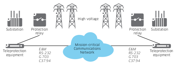
Teleprotection for power systems protection has been deployed by utility companies for many years. It’s purpose is to monitor the condition of the Electricity Grid, isolate faults, disconnecting faulty parts from the rest of the network and thereby prevent damage to critical parts of the power infrastructure.
Teleprotection is a physical interface between the telecommunications equipment and the electrical grid protection relays. When a fault occurs, the protection system switches on circuit breakers or reclosers to avoid a fault rippling through the network. Also, in the event of an outage, teleprotection helps restart power to a part of the grid.
Early teleprotection systems used voice-frequency signalling technologies. These were replaced by digital electrical Tele-Protection Signalling (TPS) equipment using 4 or 8 command channels encoded into a 64kbit/s standard digital data channel, in accordance with the ITU-T G.703 recommendations. This brought dependability and interoperability of systems, meaning that dedicated channels were no longer required as any standard digital transmission network could be used, separate from the power system.
This was later enhanced by the development of Tele-Protection Systems with Optical (TPSO) interfaces, which allowed the direct fibre connection between the teleprotection device and the primary multiplexer.
The IEEE C37.94 standard for TPSO interfaces
The IEEE C37.94 standard defines an optical fibre interface for use between teleprotection systems and digital multiplexer equipment, operating at a data rate of nx64kbit/s.
This allows the interconnection of different vendors teleprotection equipment with different vendors multiplexer equipment, without any restriction on the content of the nx64kbps data, using up to 2km of 50μm or 62.5μm multimode (or up to 20 km of 9μm single-mode) optical fibre.
Critical Systems deployment
Teleprotection systems are typically installed in high-voltage transmission grids where distances are usually greater than in distribution grids and play a critical role in preventing instability in the grid and damage to expensive substation equipment.
Teleprotection systems monitor conditions on transmission lines and coordinate tripping of the transmission lines to quickly isolate faults.
A teleprotection system usually has two components: a protection relay, which executes the actual switching; and the teleprotection equipment itself, which is the interface to the mission-critical communications network.
Typical Teleprotection Systems Network
To ensure that the power systems are properly protected, real-time exchange of status information messages and commands between teleprotection equipment must be reliably transferred with tightly-controlled latency over a deterministic mission-critical communications network, traditionally composed of TDM multiplexers and optical PDH or SDH equipment.
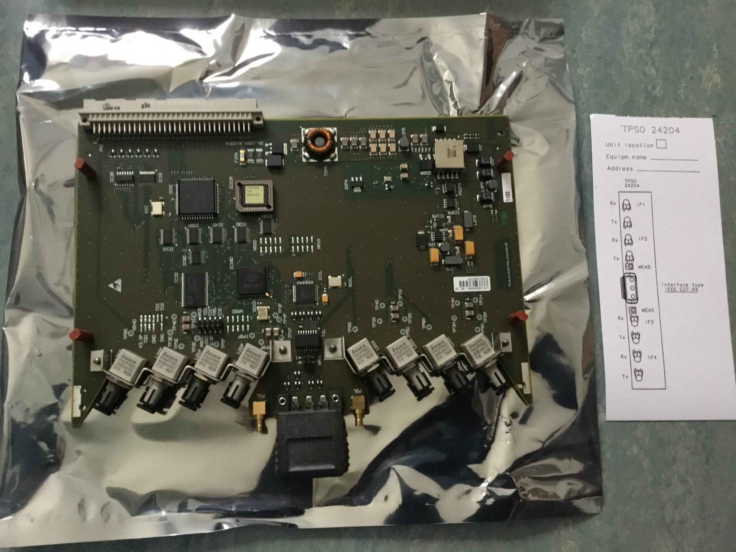
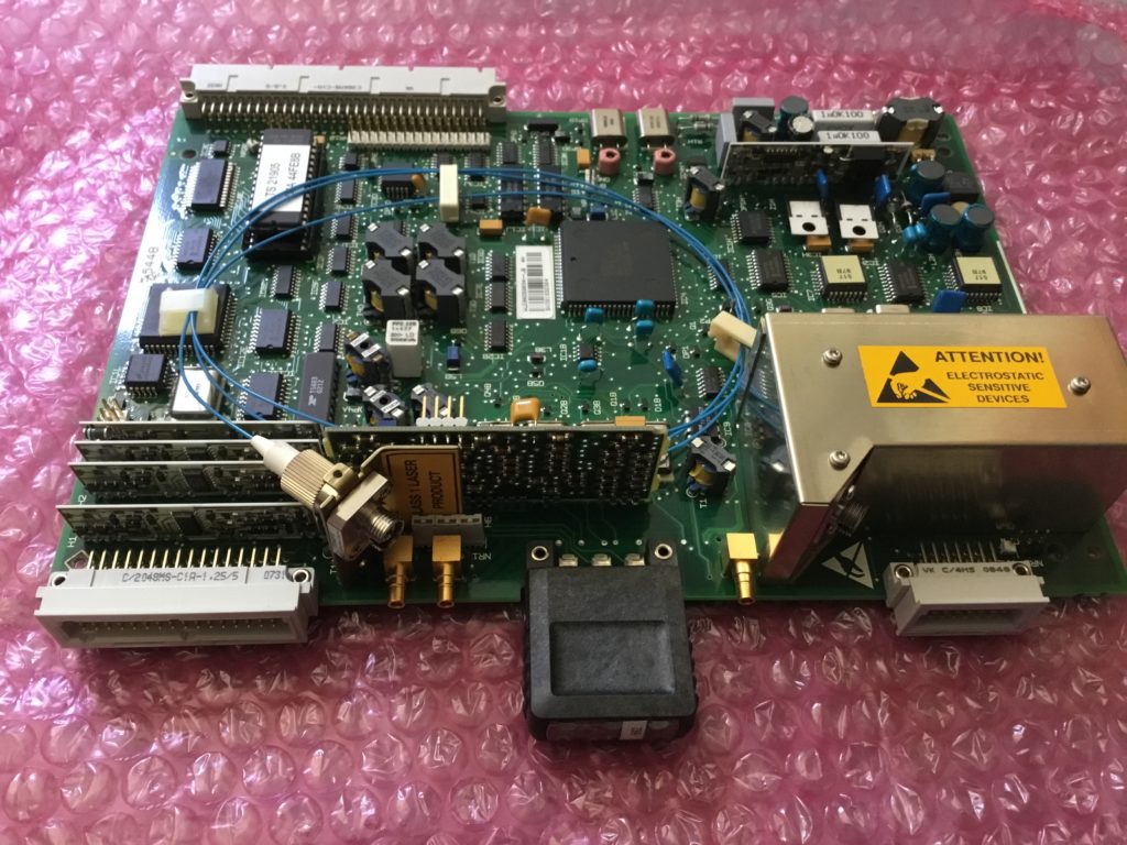
Nokia ‘Dynanet’ TPSO 24204
An example of a vendor’s multiplexer is the Nokia ‘Dynanet’ equipment family. This utilises the TPSO 24204 interface unit for connecting the teleprotection devices directly to the primary multiplexer. This provides four IEEE C37.94 standard interfaces, with nx64kbit/s optical data channels (where n is 1 to 12).
TPSO – 24204
Because of the direct connection, there is no need for a separate converter to change the optical connection to electrical. This eliminates electrical interference and data corruption caused by disturbances from the high voltage power line.
Your operational systems requirements
Let us know how we can assist you to keep your new and legacy systems operational with technical support, repair services and equipment spares. We look forward to hearing from you.
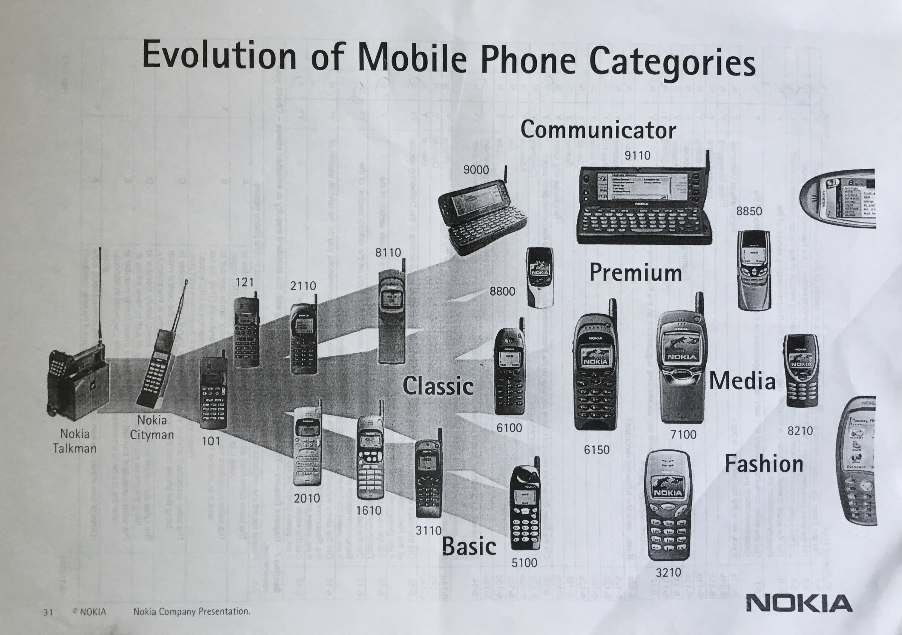
A long time ago, great “Dinosaur beasts” of Mobile Communications were supreme. The beginnings were in the 1970’s with the launch of a Motorola handset weighing 2kg. This was followed by other barely portable products with huge batteries such as the Nokia Talkman. Only for the ‘new adopters’ who had to be in touch all the time.
Then came the ‘Bricks’
From these humble beginnings, soon a range of solid, reliable but ‘bricklike’ big and heavy phones appeared, like the Nokia 2110 and the Motorola Dynatac 8000X, as featured in the 1987 movie “Wall Street”. Designed for upwardly mobile business people.
Diverse expansion
Then came a period of rapid expansion with a diverse range of more affordable products to suit wide consumer tastes. Various forms, colours and accessories became more and more important, with slide phones like the Nokia 8110 as featured in the 1999 film “The Matrix” and flip phones like the Motorola Razr, providing a ‘Star Trek’ appeal.
Feature explosion
An expansion of more and more features to make mobiles do more fuelled the explosion of product ranges. Cameras and music players were added to increase the functionality of these increasingly sophisticated and compact pocket-sized devices, such as the Nokia 6230.
Nokia 6230
A glance at the 2004 Carphone Warehouse catalogue shows how varied mobiles had become, with the top 10 dominated by Nokia, Sony-Ericsson, Siemens and Motorola as the biggest manufacturers of the time.
2004 Carphone Warehouse “Top 10”
‘Tyrannosaurus’ functionality heavyweights
For a while, the king of the land was the bulky, terrifyingly expensive but impressive (for its time) Nokia Communicator, offering phone, text, email and even fax. Opening up to reveal a full QWERTY keyboard, the range started with the 9000 which appeared in the 1997 film “The Saint” and had evolved by 2007 into the even more powerful E90.
Nokia E90 Communicator
Extinction Event: The Death of the incumbents
But then came biggest shock to the world of mobile communications: the launch of the first Apple iPhone on 9th January 2007.
Like a meteorite striking the earth, this shock spelt the end for many mobile types which couldn’t compete with the sudden demand for ‘touch-screen’ devices using apps.
Indeed companies like Nokia, once the biggest of them all, couldn’t adapt and died a death, as well documented in the BBC documentary “The Rise and Fall of Nokia”
Survival of the fittest
The ‘smartphones’ from Apple and later Android-based from the likes of Samsung became an increasing hit, wiping out much diversity and seeing a seismic shift away from many form factors to the now standard “slate” style of device.
Apple iPhone 4
Some ‘featurephones’ as they came to be known have lingered on, and in recent years companies like HMD global, who under licence have taken some iconic Nokia designs such as the 3310 and made a successful relaunch. Diversity is now finally creeping back with new variants such as the ‘folding’ Samsung Galaxy Z Fold2.
Your Paradigm shifts
Any memories or stories to tell? @YellowsBestLtd would be keen to hear your thoughts and experiences of sudden technology ‘paradigm shifts’. Let us know if we can be of any assistance with your future solution or services requirements.
It’s almost difficult to believe that not so very long ago (ok, going back maybe more than 50 years) there were no optical fibre or digital transmission paths of any flavour of technology providing our communications infrastructure.
Analogue FDM
From early to mid 20th Century, an extensive core copper cable network was rolled out, based on analogue FDM (frequency Division Multiplexing) over coaxial pairs, with the valve-based technologies occupying a lot of space and consuming much power.
Digital PCM
The late 1960s saw the introduction of digital PCM (Pulse Code Modulation) sampling at 8kHz. The ITU-T (International Telecommunication Union – then known as CCITT) standardised 30-channels at 64kbit/s in a 2.048Mbit/s multiplexing system, using 8-bit A-law algorithm (the USA adopted 24-channel 1.544Mbit/s with μ-law algorithm).
Problems with high bit-rates
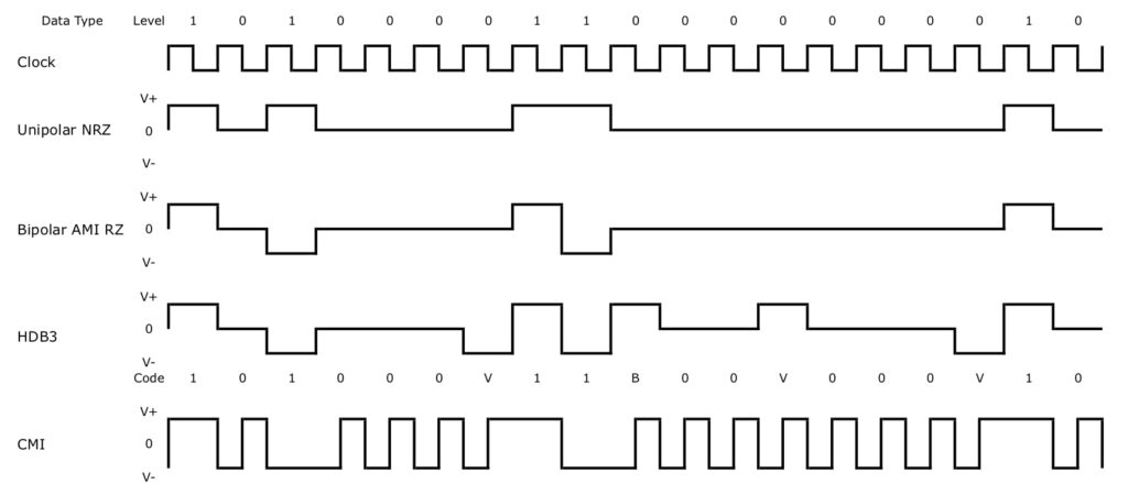
The higher bit rates gave rise to crosstalk interference problems on many existing cables. Also, data signals transmitted as voltage levels in unipolar NRZ (Non-Return to Zero) format are not self clocking and have a significant DC component, wasting power. Bipolar RZ (Return-to-Zero) type AMI (Alternate Mark Inversion) coding prevents the build up of the DC-component for longer distance and addresses the issue of data containing multiple ones. However, long sequences of zeros still present problems with a lack of transitions causing difficulties maintaining synchronisation.
Introduction of Line Codes
Line Coding of the format mB-nB was introduced to overcome these issues. Initially 4B3T (four Binary, three Ternary) was used. This encodes each 4-bit input group into a 3 symbol output using the three states of positive, negative and no pulses.
e.g. ‘0000’ is coded as ‘+0-‘
This improved efficiency in terms of bit per symbol over AMI, which itself is an example of a 1B1T code. Improvements in transverse screened cables were also made. However, transmission problems with high-speed digital data were still encountered due to unsuitable copper cabling which needed to be addressed.
PDH Higher Order Multiplexing
By the late 1970s, the UK had adopted the ITU-T recommended PDH (Plesiochronous Digital Hierarchy) of E-carrier higher-order multiplexing at 8Mbit/s, 34Mbit/s (in the US, T-carrier at 6Mbit/s, 45Mbit/s) and 140Mbit/s.
The lower rates of the E-carrier system adopted HDB3 coding, which replaces 4 ‘0’s with ‘000V’ or ‘B00V’ (or in the US for T1, B8ZS coding which replaces 8 ‘0’s with ‘000VB0VB’).
CMI (Coded Mark Inversion) was included in the ITU-T standards for higher-order PDH at 140Mbit/s PCM (as well as SDH at 155Mbit/s electrical STM-1). This is a 1B2B type of NRZ coding where a ‘0’ is represented by ’01’ and a ‘1’ as an alternatively ’00’ and ’11’, with +V and -V representing the coding levels.
The advantage of the coding is it makes clock recovery by the receiver simple and for maintaining synchronisation alignment with a long sequence of ‘0’s or ‘1’s.
Line Coding examples
Optical fibre systems
From the beginning of the 1980s, early optical-fibre multi-mode systems operating at 850nm were deployed, and later single mode at 1300nm, using the PDH multiplexing capacities.
Typical of long-haul PDH optical-fibre systems, the 2 Mbit/s, 8 Mbit/s and 34 Mbit/s ‘Dynanet’ products from Nokia have ITU-T G.703 compliant digital interfaces using the HDB3 code, but using an optical transmission Line Code of 5B6B. This is another type of mB-nB code, where in this case 5 bit data words are coded using 6-digit code words
e.g. ‘00000’ being represented as ‘100111’.
As well as its use on electrical systems, CMI Line Coding has also been popular for use on short-haul optical-fibre transmission such as ’tactical’ fibre optical systems operating at 2 Mbit/s.
SDH / SONET – A different approach
For optical SDH systems, STM-1 and above, scrambling is employed instead of line codes to ensure the incoming bit stream contains sufficient transitions for maintaining synchronisation. This works by combining the data signal with a pseudo-random bit sequence generated by a scrambler polynomial generator.
i.e. with a sequence of length of 127, the generating polynomial is 1+x6+x7 , leading to input data ‘00000000001111111111’ being scrambled as ‘11111110000001000001’.
Optical PDH still serving
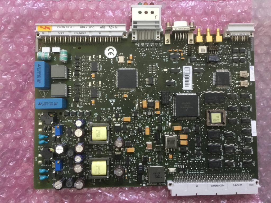
In most cases higher-order optical PDH has been decommissioned, but optical transmission at 2Mbit/s is still in operation for many low-data rate applications, where costly replacement with SDH, WDM or carrier Ethernet would bring no advantage. An example product is the Nokia DF2-8 which continues to offer reliable access services, particularly in the Utilities and Transportation industries.
DF2-8 – TA 21518
Copper systems still in operation
Though core copper electrical transmission systems have now been discontinued, much of ‘last mile’ telephony and related broadband connections are still copper access. For extended data transmission applications, copper systems are still deployed and maintained. Such products include the Nokia DSL2i copper line equipment (including power feeding repeaters) using SHDSL (Single-pair High-speed Digital Subscriber Line). This uses TC-PAM (Trellis-Coded Pulse-Amplitude Modulation) which is a 4B1H Line Coding, since translates 4 binary digits into 1 Hexadecimal (16) levels. It improves range, especially when used with regenerative repeaters, and improved ADSL (Asymmetric Digital Subscriber Line) compatibility.
ACL2i PF GEN – T65580
Feedback and assistance
This has been a necessarily very brief run-through of legacy transmission and some of the Line Codes employed. @YellowsBestLtd would be keen to hear your experiences and knowledge of transmission systems and performance of Line Codes. If we can be of any assistance with your solution requirements, including both new and legacy technologies, then please get in touch.
Most workplaces have seen some considerable disruption over the last year due to the restrictions necessary to deal with the global Covid-19 virus pandemic. Hopefully things are going to get easier over the coming months. But before we race to ‘get back to normal’ (if that’s indeed possible), let’s consider some unexpected benefits we might want to hang onto.
Work is what you do, not where you do it
Commuting has always been a drag. The time wasted driving, not to mention the cost, in order to reach an office in which documents are written, emails are read and replied to, and phones calls are made. Or instead, various ‘productivity’ applications are used. All of which could be done from home. What is needed is a ‘mind-shift’ to recognise that “I’m off to work” can mean engaging in an activity rather than physically travelling somewhere.
What’s the point of an office?
The broad acceptance that an office is where ‘work happens’ is due to the familiarly of their existence over a number of years. Once upon a time there were good reasons why work had to be so: people needed the facilities they provided, including main-frame computers, desk telephones, fax machines, printers, typing-pools (yes, really – people once didn’t type their own documents!) And memos – remember those ‘internal mail’ envelopes? But now, with laptops and mobile phones and broadband internet, it’s no longer critical to all share the same space.
People ‘like’ keeping in touch
The reality of the office is that it’s no longer a critically functional resource hub, but there are some social benefits over working remotely. It’s a place to meet and greet, share ideas and stories, help each other and generally contribute to high morale. People enjoy discussing last night’s TV or the football. Lasting bonds and relationships are formed, sometimes even being introduced to future partners. Not sure all employers would see this to be their ‘role’; the social side can of course be achieved in other ways. Anyway, flexible remote working offers the opportunity for better work-life balance.
Meanwhile, bosses like collecting their workers in one place as then it’s easier to ‘manage by walking about’. There’s a trust element: how can the staff be really hard at work if they’re not visible, aka ‘chained to the desk’. But following McGregors’s ‘Theory X (authoritarian) and Theory Y’ (participative) style of management, you either micromanage them because they’re not motivated, or trust people to take pride in their work and get the job done. So forcing people into an office isn’t the answer to productivity. Rather, pick the right people, train and support them, give them ownership of their tasks. Let them work where and when they need to. Use performance reviews as a tool (not a chore) to keep on track and set rewarding goals.
Quantity or Quality
The crazy thing about the 9-5 office culture is people vary between not having enough time to get a job done, and piloting a desk ‘looking busy’, because they’re supposed to be ‘in’. Flexible working on the other hand recognises that people have lives with things that need scheduling from time to time, around varying business demands and commitments. Allowing people the discretion to manage their work-life balance means better motivated and focussed staff who will put the extra effort in when needed. Or else, managers need to take strong decisions on appropriate resources and team composition. Working ‘smarter not harder’ certainly doesn’t mean forcing everyone into an office and making them work all hours.
Meetings expand to fill the time available
It seems like ‘work’ to spend hours in meetings showing each other an endless supply of presentation slides. Discussions often arise involving only a few participants while others wait passively. The reality is very little is accomplished that couldn’t have been better reviewed remotely, in one-to-one conversations or communicated more broadly via team or company-wide bulletins.
Keep your germs to yourself!
Due to the emphasis on ‘attendance’ (perhaps ingrained in people from their school years), there’s often a culture of ‘bravely struggling in’ when ill with a cold, thus almost guaranteeing the sharing amongst all colleagues. Above all else, the pandemic has shown the sense in keeping people separated to reduce the spread of illness.
Better for you, better for the environment
Not everyone can work from home, and certain tasks can’t be done remotely. But it’s time for a re-evaluation of what journeys are ‘necessary’ and what are the most productive work patterns, both in terms of getting the job done (without sitting in traffic jams for hours) and maintaining a flexible, motivated workforce. Not least because of the unsustainable effect on our planet’s finite resources and impact of climate change due to limitless business activities and excessive travel.
Are you ready for the ‘paradigm shift’?
@YellowsBestLtd we’d be interested to hear your thoughts and feelings about the changes brought about by Covid-19, and how you see habits changing for the future. Will you be rushing back to the office, or reaping new flexibility from remote working? Please get in touch, and let us know how we can help with your continuing business requirements. We look forward to hearing from you.