
Modern networking standardisation
For decades, various communication protocols have been utilised to connect telecommunications and computer hardware devices over short and long distances. To avoid incompatibility problems, standards were formulated and agreed, but meanwhile, a continuous drive to provide improved performance has meant an evolution of various alternatives.
Today with the dominance of USB, there are connector types and associated data protocols that have become almost universal for the wired serial connection of new devices over short-distances (when the use of wireless alternatives like WiFi and Bluetooth are not possible or appropriate). Whilst Ethernet has become the preference for local IT networks, for long-distance telecommunications, fibre-optic transmission is providing the benefits of reliable high bandwidth services.
Maintenance of legacy standards for connecting and communicating
Despite this, many older infrastructure systems and devices continue to utilise historic protocols and connections, and so it is still of benefit to recognise and be able to maintain ways to interoperate. There follows a non-exhaustive overview and comparison of the most popular standards and types of serial data communication methods.
RS-232 (V.24 / V.28)
Introduced way back in 1960 by the Electronic Industries Alliance (EIA), this is probably the longest surviving communications standard, but over time due to various revisions and lack of uniformity of connector types and connections, incompatibilities can arise. This resulted in the need for conversion cables, gender changers, etc.
It is a serial, full-duplex, unbalanced, single ended communications standard which has limitations in terms of transmission distance, noise immunity and operating speed, and can only be used for point-to-point connections.

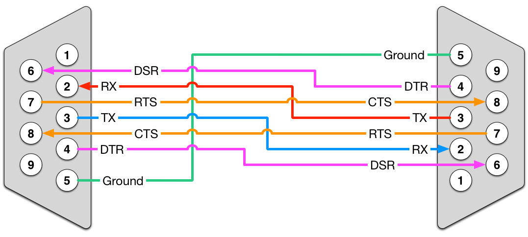
Given its age, it pre-dates most of modern computing, and was established for the relatively new purpose of communicating between a teleprinter, designated as the Data Terminal Equipment (DTE) and a modem, the Data Communication Equipment (DCE). The standard defines a range of ‘circuits’ (pin assignments) which include data – TxD (transmit) and RxD (receive) – along with various control signals such as DTR (data terminal ready), RTS (request to send) and CTS (clear to send).
When directly connecting two DTEs, such as two computers without using modems, a ‘null modem’ or cross-over cable is needed to swap the connections between the transmit / receive data and control lines.
Over the years, this extended to the uses of connecting computers to various peripheral devices like printers, as well as to other computers. Most PCs then came to be equipped with a “D-Type” port, initially for 25-pin connectors but eventually 9-pin became much more common.

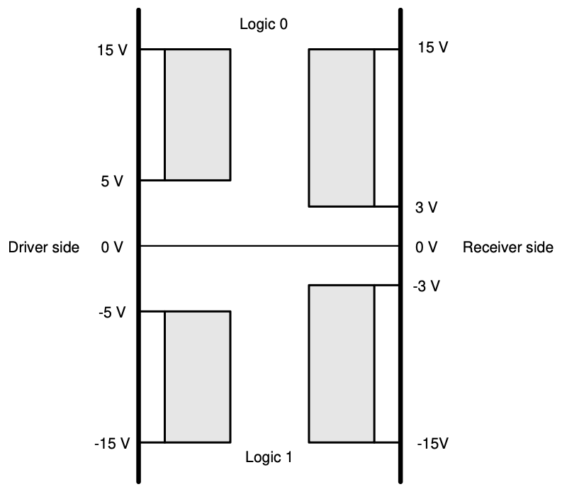
Voltage levels are defined for the signals, in the range of -3V to -15V i.e. negative voltage representing a logic ‘1’ (mark) and between +3V to +15V i.e. positive voltage as logic ‘0’ (space). The range between -3V and +3V as invalid, and typically voltages are expected between +/5V to +/-12V whilst peak voltages can up to +/- 25V.
RS-232 TTL
This variant to the RS-232 standard is designed for more convenient interoperation with low voltage circuits over shorter transmission ranges. This specifies a positive voltage of +5V representing logic ‘1’, and 0V for logic ‘0’, which unfortunately can cause operational difficulties through confusion regarding the deployed types. Naturally, this requires correct interfacing and use of converters to provide the required voltage level shifting and inversion between variants.

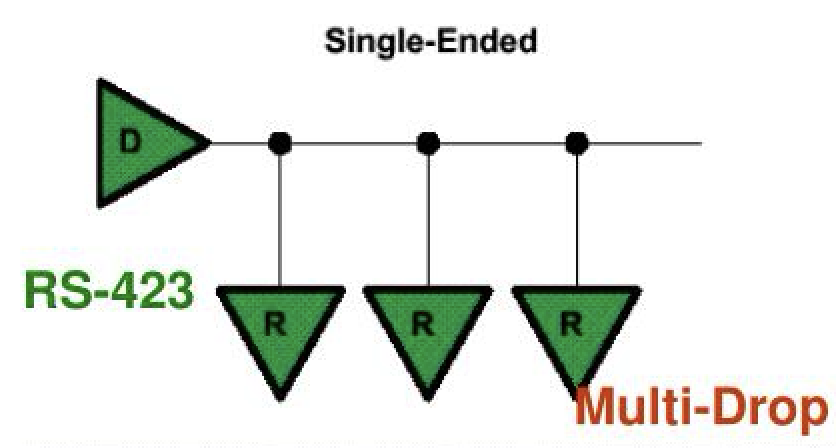
RS-423 (V.10 / X.26)
Originally designed and launched in 1975 as a replacement for RS-232, offering longer distance and faster speed communication, it failed to become widely adopted. It did however feature on the BBC Micro in the 1980s, utilising an unusual 5-pin DIN connector.

Sharing similarities with RS-232 as a serial, full-duplex, unbalanced, single ended communications standard, it notably adds multi-drop capability, making it possible for one transmitter to send data to up to 10 receivers. It’s voltage range is restricted to +/- 6V, with the driver output between +3.6V to +6V representing logic ‘0’ and -3.6V to -6V for a logic ‘1’.
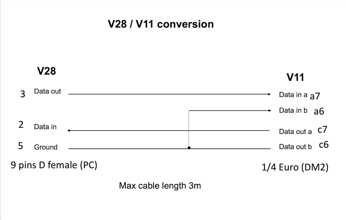
RS-422 (V.11 / X.21)
This standard, also launched in 1975, provides serial, simplex, balanced, differential communications. Like RS-423 it provides multi-drop capability for one transmitter and 10 receivers.

It was more successful as an upgrade to RS-232 as it provided better noise immunity through the use of twisted pairs of conductors carrying two differential data lines. Full-duplex communication is provided by using 4 wires and two transmitters and two receivers to send the data in both directions.

The differential voltage between the pair of transmit lines and pair of receive lines determine the logic states, rather than the nominal 0V to 5V signals compared to ground, with the maximum common-mode voltage in the range +/-7V.

Typically, line A (or Y) is labeled TxD- / RxD- and is the non-inverted signal and line B (or Z) is TxD+ / RxD+, which is the inverted or complement of the same signal. Then B greater than A usually represents logic ‘1’, following the RS232 convention that this state is represented by a negative voltage, in this case line A of at least less than -0.2V with respect to B. Conversely, A higher than B by at least more than +0.2V, therefore represents logic ‘0’.
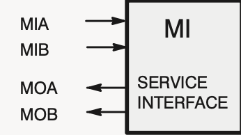
It is important to assign these lines correctly; for instance, on a Nokia DM2 multiplexer, the UR / UT specifications for the MI service interface assign logic ‘1’ to a negative voltage, but this doesn’t make it clear whether this is referring to B >A or A > B. In practice, this can be addressed simply by reversing the two input and/or the two output A & B connections should the opposite assignment apply.
RS-485
This standard came out in 1983, and brings further enhancements over RS-232 whilst retaining a degree of backwards compatibility with RS-422. It provides serial, semi-duplex, balanced, differential communications. Like RS-422 it uses twisted pairs of differential data lines to provide improvements to transmission distance, noise immunity and operating speed. But through use of bidirectional transceivers, it only requires 2 wires to provide both directions of data transfer (though not at the same time, i.e. semi-duplex).
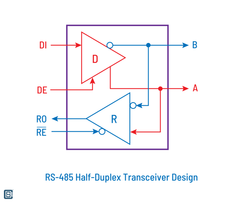
This can be upgraded to 4 wire full-duplex operation by adding an additional pair of transceivers, but in practice this is not necessary unless for interworking with existing RS-422 components. It extends transmission capability to true multi-point communication, with the possibility for use of up to 32 transmitters and 32 receivers, by means of a tristate mode so that drivers are switched off when not transmitting.

Usually, line A is named D- as the non-inverting signal and line B is its complement, the inverted signal named D+, such that when the voltage of D+ is high, D- is low. With B greater than A by +0.2V then this represents logic ‘1’. The opposite polarity, resulting in a voltage difference of B lower than A by -0.2V, is therefore logic ‘0’.
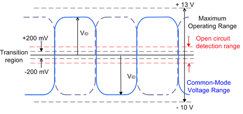
Its improved maximum common-mode voltage range of -7V to +12V aids its ability to operate in multi-point configurations, allowing for wider differences in ground potential between the drivers and receivers.

Conversion between RS-422 and RS-232
This naturally loses the RS422 advantages of differential data for noise suppression and transmission distance.
For RS232 a negative voltage is logic ‘1’; when the device transmits this to the RS422 RxD- or A input the differential voltage with respect the RxD+ or B input held at GND is B > A i.e. logic ‘1’. Whereas with a positive voltage from the RS232 device the RS422 input differential voltage is A > B, equating to logic ‘0’.
However, when the RS422 TxD- or A output is low it could be the case that this not as negative a voltage as the -3V the RS232 device is expecting, and so technically is invalid according to the specification. However, in practice for many devices their operating threshold is beyond -1.5V and since B > A it is interpreted anyway as logic ‘1’. When the RS422 TxD- or A output is high, A > B which results in logic ‘0’ at the RS232 receiver.
Interconnection of RS-485 and RS-422
Since RS-485 transceivers are generally ‘backwards compatible’, they can be applied to interface with existing RS422 devices. For full-duplex communication, 2 transceivers are used in the 4-wire configuration of RS422, and the semi-duplex capabilities of RS485 are ignored. Plus the RS422 restrictions of only one driver and up to 10 receivers per transmission direction apply.
The RS422 driver TxD+ and TxD- lines are respectively connected to the D+ and D- pins of a RS-485 device acting as a receiver. Similarly, the D+ and D- pins of a RS485 device acting as transmitter are connected to the RxD+ and RxD- lines of the RS422 receiver(s).
Comparison with USB
Whilst USB has become the De Facto standard for modern short distance wired connections, it is useful to compare this against the legacy protocols in order to understand the similarities and differences, and why it may be important to maintain or even extend existing interconnections.
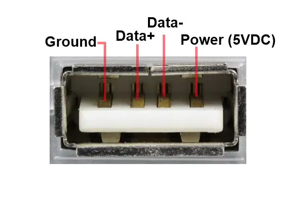
USB 1.0 / 2.0 provide serial, semi-duplex, balanced, differential communications, analogous to RS-485 whilst offering much faster communication packaged in a smaller and more convenient 4-pin form-factor.
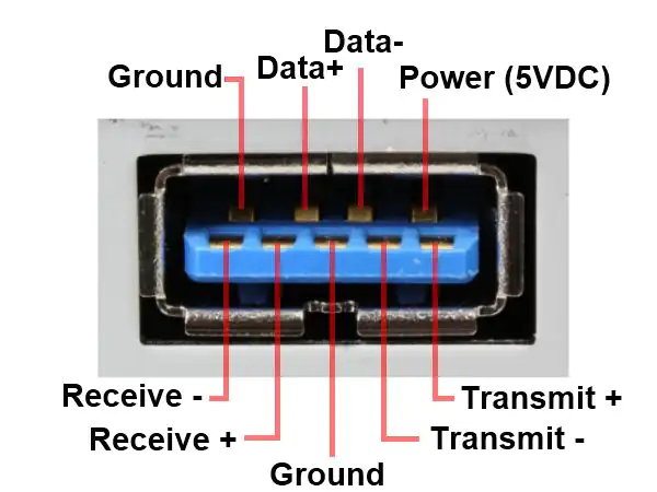
USB 3.0 uses two additional pairs of conductors in a compact 9-pin connector to operate full-duplex like RS-422, whilst maintaining backwards compatibility with older USB connections, and provides various further improvements including even faster ‘SuperSpeed’ transmission.
However, USB only provides for point-to-point connections, with lower power and limited to TTL voltage levels, and as a result shorter transmission distances.
In conclusion, the choice of use depends on the various differing applications such as the interconnection of computer peripherals, industrial control, remote monitoring and multi-device connections.
Consequently, for legacy interworking and improved performance over longer transmission distances with wider voltage ranges, dedicated USB to RS-232 / RS-423 / RS-422 / RS-485 converters are available.
Keeping Customers Operational
@YellowsBestLtd with our aim of Keeping Customers Operational assist with seeking out new products and legacy equipment spares to maintain new and well-established systems, as well as built-to-order cables and connectors to suit exact requirements.

We would be keen to hear your experiences of using communications protocols and whether we can be of any assistance with your solution requirements for legacy systems and new technologies, so please get in touch!