Views / News – Blog

Trade Shows and Industry Events

Although often busy with immediate actions and therefore time can become short, throughout the year it’s good to make the effort to attend a number of the multitude of trade shows and industry events held throughout the year. They can be helpful for finding out about industry developments and trends, products and services and generally networking with Customers and Suppliers.

There follows a non-exhaustive list of a few held recently in the U.K. Where possible, dates for next year’s events are included which should help with next year’s diary planning. If you’re going we could meet up, and if you’re exhibiting then do advise so your stand can be visited! Always keen to find opportunities and occasions to discuss how services and solutions can be best aligned for mutual success.


@CloudExpoEurope – March 2017 at ExCel, London.

The cloud event for business. Includes #CloudSecurityExpo, #BigDataWorld, #SmartIOTLondon, #DataCentreWorld.

Next scheduled for 21st & 22nd March, 2018, ExCel, London.


@Railtex – May 2017 at the NEC, Birmingham.

The UK’s International Rail Industry Exhibition. Specialising in the latest equipment, systems & services.

It’s sister event @Infrarail will be held 1st-3rd May 2018 at ExCel, London.


@TechXLR8 – June 2017 at ExCel, London.

#TechXLR8 is a festival of technology, connecting industries and enabling new thinking. Part of London Tech Week #LTW 2017.

Next scheduled for 12th-14th June 2018 at ExCel, London.


@IPEXPO Europe – October 2017 at ExCel, London.

Europe’s number one enterprise event. Includes #CloudEurope, #CyberSecurityEurope, Networks & Infrastructure Europe, AI Analytics & IOT Europe, #DevopsEurope, Open Source Europe.

Next scheduled for 3rd-4th October 2018 at ExCel, London.

Also IP Expo Manchester is on 25th-25th April 2018 at Manchester Central.


@EngDesignShow – October 2017, Coventry.

The #EngineeringDesignShow is the UK’s must-attend event for engineering, and also includes #ElectronicsDesignShow and #EmbeddedDesignShow.

Next scheduled for 17th-18th October 2018 at Ricoh Arena, Coventry


@IETAwards Ceremony, London.

Celebrating and networking as the winners of the #IETAchieve prestigious Achievements Awards and Scholarships are announced.

Held on 15th November 2017, at The Brewery, London – Read the review!

Next years’ @IETawards Ceremony will be held on 14th November 2018 in London.


Please contact us to let us know your plans for the coming year ahead, and perhaps we’ll meet up!

Repair Services

Although many industrial infrastructure solutions tend to be very reliable and long-lasting, from time-to-time system components can become non-operational, and when these cases arise, businesses benefit from professional repair services.

Equipment requiring repair services falls into two categories:

  • Recently deployed systems, which are still in production by the Original Equipment Manufacturer (OEM).
  • ‘Legacy’ systems, where the production has ceased; in some cases even the original vendor is no longer in business.

For the first category, certainly where there is a residual warranty provision, it may be best to return the failed item to the OEM for repair or replacement. However, businesses may still benefit from an alternative or supplementary service provision, particularly when the vendor’s production facilities are located overseas, and repair and return times are long (typically in excess of 30 days).

Regarding the second category, fortunately there are a range of options that YellowsBest, together with its network of independent service providers, can assist businesses with their ongoing support needs, to maintain the operational nature of their systems and thereby maximise their investment in deployed infrastructure.

YellowsBest assists customers with a wide variety of infrastructure elements, including telecommunications cards, CCTV cameras, matrix displays, etc. There are a number of ways YellowsBest can provide repair services:

  • Component-Level Repairs
  • Swap Repairs (Entire Module substitution with Spares)
  • Functional Replacements (Complete system substitution with compatible alternatives)

There follows brief descriptions of these repair services that we have been providing to our customers. We would be very pleased to hear from you should you wish to discuss your requirements; please contact us to see if we can be of assistance.


Component-Level Repairs

From time-to-time, hardware elements within infrastructure systems fail, and repair services are required. The diversity of modern networks and technologies in use by businesses means that there are a wide range of parts procured over a considerable period of time, from a multitude of vendors and international manufacturers from across the globe. This means that there is a spectrum of the relatively new to aging items, some parts being still under warranty to elements from OEMs that no longer exist.

YellowsBest is able to provide a comprehensive repairs management service, assisting business by acting as a single returns facility for both new and old equipment items. Typically, newer parts in or out of warranty will be sent to the OEM for repair or substitution. Older items, especially in the case where the OEM is no longer exists, will be repaired using our network of independent service providers, all to a standard equivalent to the original working condition and warranted operation.


Swap Repairs

Sometimes the repair of equipment elements is not possible, such as when the item is physically damaged or Beyond Economic Repair (BER). Or it can be the case that the repair times are long, and in order to safeguard continuous operations of systems, additional parts can be used for substitution when failures occur.

YellowsBest can source the required equipment spare parts, though its partnership with key vendors of the latest products as well as suppliers of legacy systems components. In many cases these parts can be newly manufactured to order and delivered within specified lead-times, or quickly despatched from either unused surplus stocks or ‘2nd user’ items, particularly in the case when systems are deemed obsolete and are no longer produced by the OEM.

With such a ‘swap service’ in place, the operational status of the deployed equipment can be restored without delay. YellowsBest can then, in many cases, obtain a component-level repair for the substituted item, and thereby return the original unit to ‘stock’, ready to provide the next swap repair.


Functional Replacements

When systems have reached the end of their useful working life, repairs are challenging and spares are unattainable, companies may need to completely change out or upgrade their infrastructure equipment.

YellowsBest can assist businesses by seeking alternative product solutions, in the form of either complete replacement systems, or re-manufactured elements to provide the most efficient substitution of equivalent required functionality. Particularly in the case where operational requirements have not changed, it may prove commercially beneficial to replace like-for-like products. In many cases, the substitution of functionally equivalent newer elements may pay for themselves over time through efficiency savings due to lower power consumption, etc.

Professional CCTV Cameras

In response to a strong demand for a diverse range of Professional CCTV cameras, we are providing both new and refurbished ‘legacy’ models from a number of manufacturers, to suit our clients’ exact requirements.

Industrial and professional use dictates key features such as a robust weather-proof housing, excellent optical quality, Pan Tilt & Zoom (PTZ) with high magnification, plus options including wiper (for clearing the lens), heater (for extended operating temperature range) and privacy masking. To support existing deployed networks, matching the communication protocol is critical, as well as the appropriate video standard (e.g. PAL).

There follows descriptions of some of the cameras YellowsBest has recently sourced and supplied to our customers, however, we are always keen to receive further enquiries and seek to provide alternatives as necessary; please contact us to discuss your requirements.


Bosch MIC series PTZ cameras

The MIC Series are best-fit cameras for high quality surveillance security applications, installed into the harshest of environments, thanks to its IP68 rating. This tough and vandal-resistant casing provides protection from the elements and physical attack. An integrated, long life silicone wiper, and a reversible rain shield ensure high quality images regardless of the installed environment.

The brushless-motor technology offers ultra-reliable operation with full 360º continuous rotation pan and 186º tilt control for exceptional viewing capability. Small increment pan speeds from just 0.2º per second to 120º per second gives the user precise control. This speed control is especially important when used with video analytic systems, particularly for tracking subjects when fully zoomed in. The MIC Series cameras are simple to integrate and use within systems that already use Bosch AutoDome cameras.

Typical of the range of products meeting professional needs, Bosch cameras have been available for a considerable time, and whilst continuing to fulfil the same basic requirements, have undergone a number of changes over the years in the portfolio which are important to understand. In particular, Bosch previously acquired the range of cameras from ‘Forward Vision’, and consequently it is critical when sourcing additional units to match the communication protocol in use i.e. FV, Pelco or Bosch. The main models (ranging from previously produced and currently available) include:

  • MIC-300 Series
  • MIC-400 Series
  • MIC-500 Series
  • MIC-550 Series
  • MIC-612 Series
  • MIC-7000 Series
  • MIC-9000i Series

There are also two product families, the ‘Classic’ standard camera and the more advanced ‘Professional’ series.

Therefore it is worth analysing the structure of the full model number in detail to ensure all requirements are met:

EXAMPLE MODEL NUMBER: MIC-500-AL-B-U-R-1-4-6-18-P

Explanation:

MIC – Metal (IP68 weather proof housing)

500 – Camera series (e.g. 300, 400, 440, 500, 550)

AL – Case Style (AL = Aluminium, STS = Stainless Steel, IR = Infrared LEDs included)

B – Colour (i.e. Black, Grey, White)

U – Configuration (C = Cantered, U= Upright)

R – Protocol (W = Forward Vision, P = Bosch, D = Pelco P/D, R = multi-protocol (S/W selectable))

1 – Wiper (1 = Wiper fitted, 2 = No Wiper)

4 – Heater (3 = Heater fitted, 4 = No Heater)

6 – Privacy masking (5 = Privacy fitted, 6 = No Privacy)

18 – Optical Zoom (18x, 28x, 36x etc)

P – Video standard (i.e. PAL, NTSC)

Not all options were available for all camera types, and the above model numbering applies to the ‘Classic’ series products. For the ‘Professional’ series, the ‘UR136’ part of the above number is omitted, since these models are by default Upright, multi-protocol units with the Wiper, Heater & Privacy functions included. Hence the part number is shorter, e.g. MIC-500-AL-B-18-P.


360 Vision Technology ‘Predator’ cameras

Since its inception in 2002, 360 Vision Technology has developed an extensive range of analogue, high definition IP, white light, infrared, cooled and uncooled thermal, polished stainless steel and radar controlled CCTV surveillance cameras to suit a broad range of general and harsh environment applications across many market sectors.

The Predator is a high performance, fully featured range of ruggedised PTZ Cameras designed and manufactured in the UK. The Predator range comes with multiple protocols as standard allowing quick and simple integration with many leading DVR’s, matrices and IP VMS systems. The Predator range covers all applications with a comprehensive range of models including analogue, HD, Thermal, Radar, and Stainless Steel versions. Predator cameras can be supplied in any colour, in any quantity.

Key features:

  • NEW Sony Starvis Modules – Ultra low light performance
  • ONVIF 2.4 Profile S Fully Compliant
  • Full Web Server Set Up
  • 1080p Full HD 2MP
  • 30x and 20x Optical Zoom options
  • Ultra Low Light options (0.1Lux colour)
  • ANPR compatible
  • Privacy zones as standard
  • High Light Suppression to eliminate glare from vehicle headlights and other bright objects
  • High quality accurate motors
  • Colour / mono, Analogue and IP camera options
  • Triple Slip Ring technology for preset accuracy and smooth movement
  • Rain Guard around the optical glass to reduce water on the screen
  • IR option for 400m illumination
  • Dual IR & White Light LED Option for 250m (IR) 250m (White Light)
  • Wiper option with programmable wipe settings
  • Washer option
  • Inverted or upright mount
  • Easy & quick setup software
  • UK supported and supplied
  • Colour at Night™ Technology for true colour at night
  • Unique alarm activated White Light illumination for enhanced CCTV Surveillance
  • Any colour Paint & Finish options
  • Marine Paint Preparation with 10 Year Paint Guarantee


Ganz ZC-YX/NX270 Series – 700 TVL Digital Day/Night  cameras

These high performance camera features Ganz GX5 technology, combining 700TVL, WDR (wide dynamic range), intelligent image enhancement and advanced OSD controls. These highly sensitive cameras are designed to deliver an unprecedented level of resolution, sensitivity and control for optimal video surveillance in all conditions.

Key features:

  • 700 TVL Super High Resolution
  • Extremely High Sensitivity Day/Night mode 0.07 lux (colour), 0.007 lux (B/W)
  • Super Low Light Performance 0.00015 lux (Sens up, 512x mode)
  • Automatically switches between 4 pre-programmed profiles for best image results
  • Smart Day/Night mode synchronizes with IR LED
  • 2D/3D Digital Noise Reduction
  • Test Pattern Output with colour bar
  • 12VDC or 24VAC Operation, Auto-Sensing
  • UL Listed
  • A time saving Pro-Pak kit is available for outdoor installations, including camera and a selection of Day/Night compatible varifocal lenses pre-installed in a rugged outdoor housing
  • True WDR, Digital Day/Night and True WDR, True Day/Night models also available.

Consultancy Services

A flexible approach to Consultancy provision

It has been a pleasure providing consultancy services to a client who was looking to develop their product sales business. YellowsBest’s approach is to tailor what we provide to meet the Customer’s exact needs. Several stages of activities were therefore established, reviewed and amended before these ‘workpackages’ were acted upon.

Strategy Workshop to identify the requirements

To thoroughly establish and document the ‘needs’,  a relatively informal but comprehensive ‘workshop’ was held.

This produced the ‘framework’ for the consultancy provision and provided an invaluable tool for measurement of progress toward the goals which were documented as part of this process.

Undertaking key tasks to assist Strategy implementation

A number of tasks were undertaken on behalf of our client in order to assist with the putting into action of the documented strategic aims.

Naturally, the implementation and development of a sales Strategy is a long-term undertaking, and YellowsBest is able to provide ongoing support to its clients with the assistance they need, as and when required, in order to ensure long-term success.

Summary of assistance YellowsBest can provide

YellowsBest is able to assist companies by providing consultation advice for a wide range of initiatives, such as:

  • Creation of Business Plans for identifying markets, customers and strategic propositions
  • Sales Strategy formulation for the generation of prospects and reaching customers via direct and channel approach
  • Assistance with key sales and business development tasks, including customer enquiries and presentations, liaison with vendors, attendance at industry events and content creation for websites and marketing initiatives
  • Performance Measurement analysis to understand success ratios and identify corrective actions to improve utilisation of resources and optimise business efficiency

YellowsBest is able to provide its consultancy services on an ad-hoc day-rate basis, or as a more structured project-delivery, over a number weeks or months as appropriate.

YellowsBest can also provide a range of other related Management Services, including Account Management, Bid Management, Business Development, Channel / Vendor Management, Commercial / Contract Negotiations, Sales and Marketing, Solutions Engineering and Training.

Nokia ‘Dynanet’ – Still Operating, Still in Demand!

Nokia ‘Dynanet’ PDH Telecommunications Product Portfolio

Still Operating, and Still in Demand!

We’re pleased to have recently helped Customers locate additional spares of this incredibly reliable and therefore popular telecommunications infrastructure equipment.

The range was originally produced by Nokia, and has been extensively deployed and in operational service around the world for over 20 years. It has formed the backbone of PDH and Access networks for many Customers across the Telecom Operator, Utilities and Transportation market sectors.

Recent Requirements

We’ve recently supplied Customers with these spare parts:

  • Smart Branching Unit (TU 21743)
  • DC/DC converter -24..-48V / -48V,-60V (21263)

These represent popular choices, but see below for an extended list of other immediately available items.

Future Dependability

It makes sense for Customers to use these spares as replacements as well as to add additional capacity to their existing networks, given the faultless performance of the products, rather than undertake costly and time-consuming wholesale replacements, given that in many case their basic telecommunications  requirements have not  changed.

Plus the ‘Dynanet’ product range has proven itself to be dependable over an extended period. How many of the latest products will be available in 5 or 10 years’ time, let alone in over 20 years?

Dynanet – an overview

 Nokia DYNANET is a family of multiplex, branching, cross-connect and line equipment.

The DM2 equipment has been designed for multiplexing analogue speech and signalling as well as data channels of different bit rates into a common 2 Mbit/s frame. The dynamic branching equipment DB2 and the cross-connect equipment DN2 increase the flexibility and application range in the DYNANET family.

The DYNACARD data channel unit selection covers the bit rates from 0.3 kbit/s up to 1984 kbit/s compliant with the V- or X-series of the ITU-T Recommendations. Other DYNACARD channel units provide specialised interfacing functions for Voice and Data applications.

The heart of the equipment is a MUX unit which is common to all channel and special units of the DM2 system. The MUX unit communicates through a 2 Mbit/s internal bus with the tributary units and carries out the 2048 kbit/s framing according to ITU-T G.732 standard.

The common MUX unit also inserts the signalling information into time slot 16 or provides the time slot 16 as a 64 kbit/s data interface, e.g., for use with a separate signalling equipment.

Analogue and digital services are realised with interface-specific channel units that connect to the DYNACARD bus. The channel units contain from one to ten voice channels, depending on the complexity of the interface.

Each individual voice or data channel can use any 64 kbit/s time slot, several time slots or only part of the capacity of one time slot. The allocation of time slots to different voice/data channels is independent of physical unit placement.

The DYNACARD VF channel unit selection provides analogue interface with signalling adaptation ranging from subscriber signalling to various types of junction line signalling. The signalling can be either channel associated or common channel signalling. In subscriber applications subscriber line testing is also available.

Immediately available from Refurbished Stock

Here is a list of items currently available from refurbished stock. All in excellent working condition, and can be delivered in a matter of days. No long lead time! But do remember that many items may be in short supply, so worth acting now and purchasing any spares you might need to avoid future disappointment!

Part Number Description
24204 TPSO H/W Module
CC 24002 DB2 Branching Unit, B2 2×2 Mb/s 75 ohm
CC 24011 DB2 2 Mb/s Switching Unit, X2 75 ohm
CC 24111 DN2 Control Unit (CU) 75 ohm
CF 24186.09 DN2 Subrack 19″, grey-L91 EMC
CG 24170 DN2 Bus Power Unit (BPU)
CU 24013 Data Interface Unit (DIU) 2M, nx64k: G.703/704, 75 ohm
CU 24101 DN2 Interface Unit (IU2) 2×2 Mb/s 75 ohm
T30506.09 17-slot DYNANET Subrack
T30851.02 Subrack Power Adapter (SPA)
T37870.01 NDM 19in 17-slot subrack
T37882.01 NDM DC Unit (NDUe)
T37889.01 NDM Backup Unit (NBU)
T65580.01 ACL2i PF GEN Line Terminal Card
TA 21513 Optical Line Terminal Repeater 2-8 M, 1300 nm LED MM/SM
TA 21516 Optical Line Terminal Repeater 2-8 M, 1300 nm LASER SM
TC 21301 DM8 Multiplex Equipment, 75 ohm
TC 21710.01 TMS Adapter
TF 21090.09 Subrack 19″, (EMC), grey
TU 21122.5 Data Interface Unit (DIU) 48..64k V.11 10ch
TU 21125 Data Interface Unit (DIU) 48..64k with sync, X.21
TU 21236.10 Channel Unit (CU) 8ch E&M/uP: 2xe&m/vf

This represents a list of the most common elements Customers need, but please do contact us if there’s something specific you’d like us to seek out for you. Always happy to help!

Solved: UK Date Format Issue on a new Apple Mac with Microsoft Excel:mac 2008

An annoying issue (for UK users) is of the date format defaulting to US (MM:DD:YY) rather than UK (DD:MM:YY). This occurs when transferring to a new Apple Mac computer with a previously correctly working installation of Microsoft Excel:mac 2008 (from an older computer, but running the same version of OS X). In theory, there should be no change, but hidden somewhere in the setup of the new computer lurks something preventing use of the UK date format.

The problem shows itself when, in a new Excel worksheet, a date is entered, e.g. using the formula =TODAY() returns something like 11/22/16 (for 22nd November 2016) instead of 22/11/16. Worse, if an existing workbook is opened, which had previously  correctly UK-formatted dates, they are all changed to the US-variation. A particular ongoing problem is then generated when new dates are added to the sheet, as entering 1/12/16 is then taken as 12th January not 1st December 2016.

 It turns out that the issue manifests itself in any User account set up on the Mac computer EXCEPT the ‘Guest’ account, which mysteriously sets the date to the UK-format. Hence this provides the clue to solving the problem. After some searching and trial-and-error, I have identified that the issue relates to the absence of a key file: com.apple.HIToolbox.plist, which for some reason is not created when setting up a new User account (and may not be copied across if importing from another computer). Luckily this file is created when opening the Guest account, which can then be copied across to all required User accounts.

Here is a detailed summary of the procedure I eventually used to fix this date format issue:

  1. Create and open a Guest Account (if not already enabled, go to Users & Group Preferences)
  2. Go to the Library folder (it’s a hidden folder, so to find it, use Finder to go to the home folder, then select from the menu ‘Go:Go to Folder’ and type in ‘Library’)
  3. Go to the Preferences folder
  4. Make a local copy of the file: com.apple.HIToolbox.plist (e.g. onto an SD card, or external/cloud drive)
  5. Now open your desired User account
  6. Go to your Library folder (again it will be hidden, so find it as above)
  7. Go to the Preferences folder
  8. Copy the file: com.apple.HIToolbox.plist (from local storage) into this folder
  9. Quit Excel and then log out of your user account, and then log back in
  10. Next time Excel starts, UK date format will be correct!

Repair of Panasonic DMR-EZ25 DVD Recorder

Panasonic DMR-EZ25 DVD Recorder

The DMR-EZ25 is a reliable and highly-specificationed DVD Recorder, and like several models made by Panasonic somewhat special by it’s capability of being able to use DVD-RAM disks (as well as the more common DVD-R and DVD-RW) for maximum flexibility of recording and playback.

This model does however sometimes fail, displaying various fault codes, preventing use but at least giving an indication of the likely problem(s). Fortunately, it is then relatively straight-forward to disassemble using just a screwdriver, and thereby replace (or repair) the relevant component modules.

Here are the full disassembly and reassembly procedures I followed to restore my unit, which had been displaying the fault code ‘U81’, to full working order by replacing the main PCB board.

Disassembly procedure

1. Remove top panel, removing 3 screws (normal, non-washer type) at rear and two on side (big).

2. Remove front panel, which pulls off once lugs are pushed back, being careful not to break lugs.

3. Remove HDMI board, removing one screw (normal type) and then easing it out of the black connector on the main board and the ribbon cable out of its socket on the digital board.

4. Remove the SD card board, removing two washer-type screws and the ribbon cable out of its socket on the digital board.

5. Remove the rear panel, removing 6 normal screws and 2 smaller machine screws by the SCART sockets, then unplugging the FAN connector cable from the PSU board (alternatively, you can leave this connector in place and lift the panel away with the PCB board).

6. Remove the PSU board, removing the three washer-type screws and easing the black power rail connector from its socket on the main board.

7. There’s no hard disk in the EZ25 model, other products have an extra step.

8. Release the digital board from its mounting frame, there are three washer-type screws (and an empty socket where a fourth one is not present), easing it out of its black connector socket on the main board hidden underneath and then fold it over onto the disk unit keeping the ribbon cables attached

9. Remove the DV input board, removing one normal-type screw.

10. Remove the digital board metal support frame, removing four washer-type screws.

11. Remove the power button pcb, removing the washer-type screw and sliding it from the lugs being careful not to pull the ribbon cable.

12. Remove the main board, removing the four washer-type screws and the ‘hidden’ normal type screw on the front by the AV sockets.

13. The remaining disk drive unit removes from the base panel, removing two washer-type screws and lifting out with the digital board (which can be disconnected if necessary by careful detaching of the ribbon cables).

Re-assembly procedure

1. Insert main board into chassis (and also the disk drive if removed, with digital board, with two washer-type screws). There is a lug to align into a hole at the front left edge, one at the front right side and a bent lug at the rear to slide under. A ‘hidden’ (non-washer type) screw is located at the front by the phono sockets, and four more screws secure the main PCB to the chassis, all are ‘washer-type’.

2. One screw secures the power button PCB, aligned with two lugs.

3. Five screws secure the metal frame for the digital support board.

4. One (non-washer) type screw holds the DV input board which needs aligning with the holes in the main board at the front next to the phono sockets.

5. The digital board flips over with its ribbon cables in place, mounts onto the frame, tucking under the lugs, slotting the DV input board into place and pressing down onto the main (black) connector underneath.

6. Three screws secure the digital board in place (a potential fourth, in the far right corner (away from the front panel) is not present.

7. No hard disk is present in the DMR-EZ25 model (different models have this extra step).

8. The power PCB is placed into position, and it’s power rail connector presses together. Three screws secure it in place.

9. The rear panel clips securely in place. Six screws secure it, all ‘non-washer’ style and two ‘machine-type’ screws locate between the SCART sockets . The connector for the fan presses in place.

10. The SD board mounts at the front onto the digital board, with a lug and two ‘washer-style’ screws. It’s ribbon cable presses in place.

11. The HDMI board slots into place onto its black connector and its ribbon cable slots into place on the digital board. A screw on the rear panel secures it in place.

12. The front panel clips in place.

13. The top panel pushes on, slides in place and is secured by three non-washer type screws on the rear and two large flat screws on the sides.

Photos (including views of the component modules from inside the product) of this repair project are on our Facebook page.

Vero Trivolt PSU – ‘product of the month’

TRIVOLT AC/DC-converter Power Supply Unit

Manufacturer: Vero

Model Number: PK60A

Product Code: 116.010018J

Description

60 to 120 Watt switched mode AC/DC plug-in power supply with three outputs in 3 U Eurocassettes for use in 19” subracks to IEC 60297-3.

  • 3 high stability outputs, all adjustable
  • √  Safety approvals to UL, cUL and EN 60950
  • CE marked for compliance to EMC and Low Voltage Directives
  • SENSE-operation (5V output)
  • Overvoltage protection (OVP)
  • Powerfail signal optional
  • No-load and short circuit proof
  • Coded H15 connector
  • VERO standardised pinning

Specifications

  • nom. height: 3U
  • nom. width: 8H
  • nom. depth : 160mm
  • output power: 60W
  • voltage outputs:
    • V1: 5V/6A
    • V2: -12-15V/1A
    • V3: -12-15V/1A

To purchase, contact us.

Dual Beam Oscilloscope project

I am pleased to announce ‘finally’ the completion of this construction project which dates back to 1991, when it was first commenced and then ‘shelved’ for a quarter of a century. Returning to it, the most amazing thing was the intact condition of the mechanical build and electronic components, as well as the paper notes and Silvine Originals exercise book (thank goodness, what chance would an electronic ‘soft’ copy had it existed be readable now?) which had been preserved perfectly despite various moves and long-term storage.

It’s based on a design by John Becker published in Practical Electronics magazine, which appeared in three parts from November & December 1988 to January 1989. The magazine title subsequently merged with Everyday Electronics to form Everyday Practical Electronics (EPE) (and then later absorbed Electronics Today International) which survives today.

The project itself comprises the build of three main electronic elements, forming the three parts of the published design: PSU, Time-Base and Y-Drive. Coupled with these is the mechanical housing to enclose all the elements, and not least is the inclusion of a Cathode Ray Tube (CRT), which provides the traditional display device for the instrument.

Mechanical Housing

This element of the project needed to ‘come first’ as it forms a fundamental part of the construction, not only containing the PCBs of electronics but also serving as the mounting frame for the necessary controls, switches, inputs and outputs, including the display screen formed from the CRT tube. Naturally finishing this stage, including the wiring of all parts, had to wait for the completion of the PCBs and so was the ‘last part’ as well.

A suitable 19” rack style box was chosen, providing more than sufficient enclosing space, the actual constraining factor was the necessary size of the front panel. The template provided from the magazine notes was photocopied and enlarged several times from the published artwork to produce a ‘full size’ design which was then stuck to the front panel of the housing. This then enabled all the holes for the parts to be marked and drilled, including the large circular hole (formed by drilling a series of small holes in a circle) for the CRT face, which was then smoothed and lined with a split insulator from cable. The final touch to the front panel was the display screen, which was again photocopied from the magazine template, this time onto clear plastic and later pin-mounted over the CRT face hole.

Two of the PCBs (Time-Base and Y-drive, once built) were later attached to the rear of the front panel via their panel-mounting control switches, and the PSU PCB was fixed to the floor of the enclosure, as was the mains transformer. To the rear of the enclosure a mains socket, fuse and on/off switch were mounted. The CRT was mounted on a bracket composed of pipe clips and packaging tray and positioned so that the face would meet the front panel hole for the display.

PSU PCB

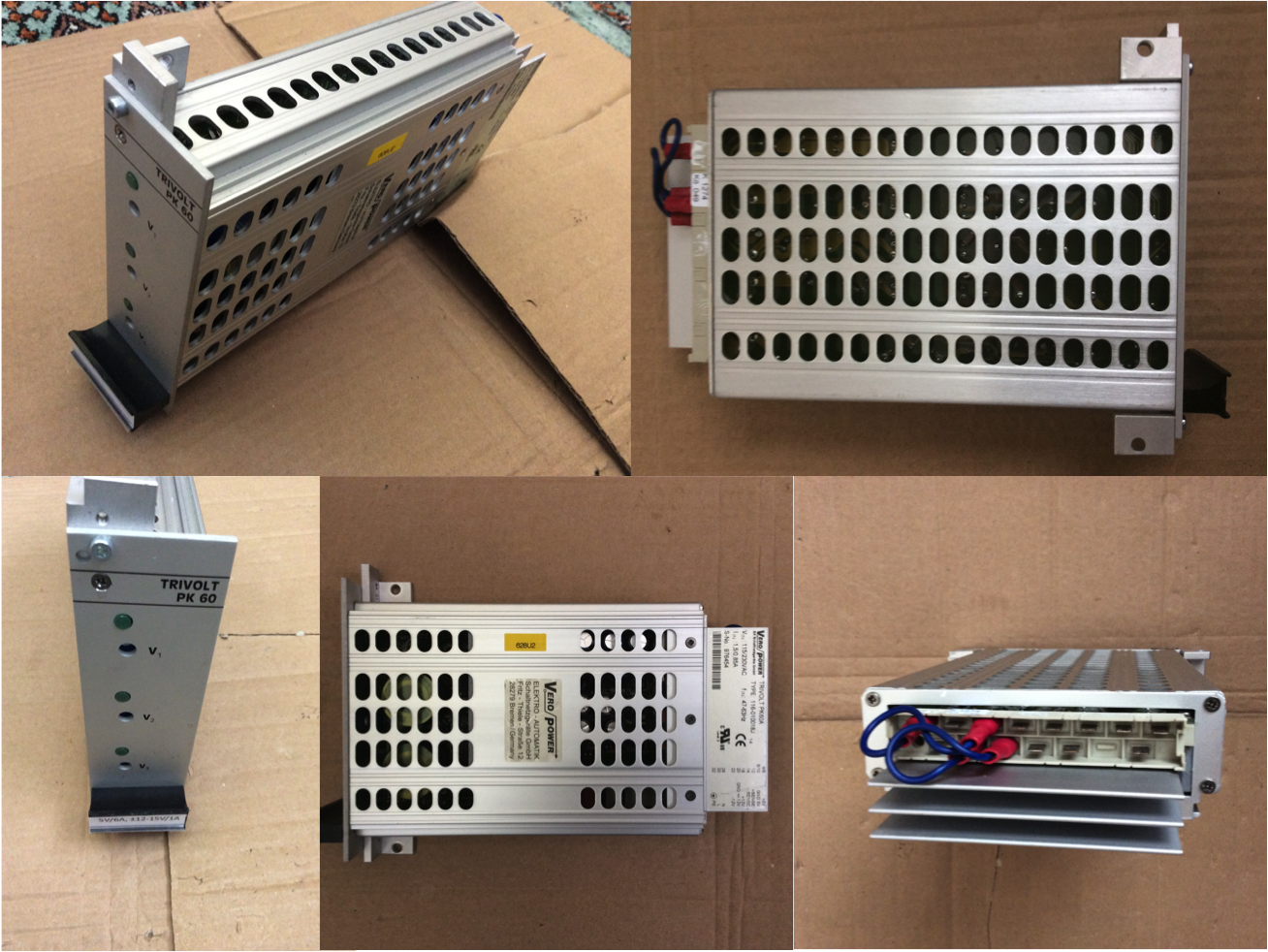
The complete power supply is formed from a PCB plus transformer to convert standard 240V AC mains supply into the +/- 5V low voltage DC supplies required by the rest of the project, and +HT 250V and –HT 350V DC supplies for the CRT display as well as a 6.3V AC supply for the CRT heater. Also produced is a 2.5V (peak) 50Hz reference signal, and focus and brilliance control voltages for the CRT.

The Mains input consists of ‘kettle lead’ socket, fuse and on/off ‘neon’ switch which were wired to the primary of the transformer, which provides secondary windings of 1x 250Vac (for the +/- HT) and 2x 6.3Vac (for the +/- 5V supplies and CRT heater voltages).

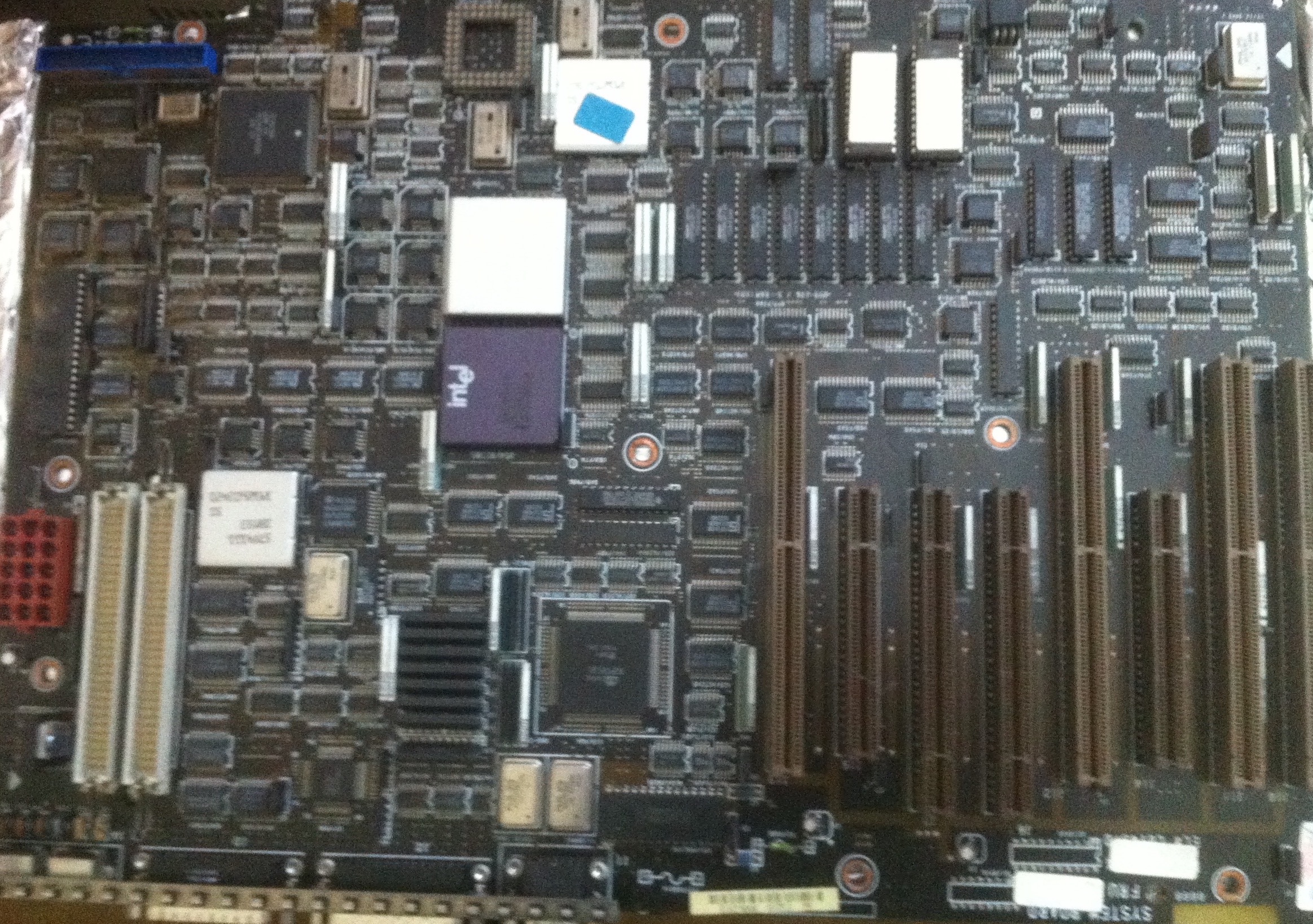
A purpose-made PCB contains all the other PSU components, including rectifier diodes, smoothing capacitors, voltage regulators, resistors and variable resistors (for adjustment of the +HT and 50Hz reference output voltages) and drive transistors, producing the HT and stabilised 5V supplies.

The construction and testing of this stage was the most personally challenging element of the project given the presence of high AC voltage and even higher DC; the +/- HT combination required to drive the CRT display amounts to 600V! Hence extreme care was made building and testing, and probing the voltages was done with much due respect and caution!

The main ‘trouble-shooting’ required at this project stage was the diagnosis of a failed drive transistor (BF259); hardly surprising since this component is responsible for the production of the +HT 250V supply, and care was needed to avoid a short circuit whilst building and testing.

Once the PSU itself was working, four ‘temporary’ 1M ohm potentiometers were wired to the CRT base to control the X and Y deflection plates. This enabled the testing of the Tube supply circuit, allowing manual up/down and left/right movement of the ‘spot’, and well as the two permanent 1M potentiometers providing the focus and brilliance controls.

Time-Base PCB

The most complicated part of the electronic design is contained with the Time-Base PCB, providing the horizontal sweep oscillator creating the left-right ‘motion’ of the beams. For the subsequent ‘fly-back’ of the X-axis beam, a saw-tooth waveform generator is employed. A collection of circuit stages make up the various elements of the required Time-Base functionality.

The Ramp-Generator circuit consists of six capacitors selected by a switch to produce a range of ramp rates, with a variable resistor providing intermediate rate variation. As the selected capacitor discharges, the first-stage comparator IC output goes high, tripping the second-stage comparator IC output high. As the capacitor charges, the first stage comparator IC output then go low, but the second-stage comparator IC initially is held high by a diode, until a transistor goes off, tripping the comparator low and starting the repeat of the sequence.

The Sync-Retriggering circuit controls the Ramp Generator, since capacitor discharging only occurs if the diodes in this stage are grounded, which occurs when a clock pulse from an internal Pulse IC or external source causes the 4013 (dual D-type flip-flop) IC output to go low. Hence the ramp is synchronised. Switches select between +/- and external/internal trigger sources, with a variable resistor setting the correct trigger level. The external sync is decoupled and limited by capacitors, resistors and diodes to the +/- 5v power levels.

The Inhibitor circuit ensures that each X-trace sweep begins at the same position. At the end of the trace flyback with the ramp generator comparator IC output going low, the output of the inverting Schmit IC goes high. A positive pulse across a capacitor resets the Sync-Retriggering 4013 IC, inhibiting the Ramp Generator operation. The Ramp starts again after the next clock pulse from the Sync-Retriggering Pulse IC.

The Auto-Retriggering circuit provides the X-trace sweep in the absence of an external signal for sync. The ramp of the X-trace restarts via a diode when the external/internal switch is closed without the need for an external signal; with the switch open, external sync only occurs. A switch selects one of six capacitors which charges once a 4013 IC output goes high until the inverting Schmit IC trips, causing its output to go low and enabling a discharge path for the capacitor via a diode. Thus the switch-selected capacitor provides sync until pulse occurs.

The CRT circuit provides the required boost to drive the 7cm display, since 21V per cm on for one plates and 37V per cm on other plates results in 147V and 259V needed; +HT of 250V is utilised. The output voltage from the Ramp Generator first-stage comparator IC is fed via a resistor and variable resistor, setting the full ramp range output, to the base of one half of a push-pull transistor pair, which provides the HT voltage to one CRT X-plate; the other is supplied by the other transistor controlled by another resistor and variable resistor, varying the screen trace position..

The Flyback-Blanking circuit ensures the beam is not displayed on the right-left ‘return journey’ by providing -50V to the CRT grid, with respect to the cathode. When the Ramp-Generator second-stage comparator IC output goes high, a BF259 transistor goes on, and a negative pulse occurs across a capacitor, with a diode limiting the positive going pulse edge.

Trouble-shooting this project stage was concerned with obtaining a working oscillator, which was achieved once some overflow solder was removed from the transistors and the -5V supply connection restored. The X-plate connections to the temporary potentiometers were removed to allow the Time-Base to drive the CRT display, with the panel mounted potentiometers centering the trace and adjusting the width across the screen.

Y-Amps/Drive PCB

Two key elements form the final PCB. The first are the two identical amplifier stages for the two Y-inputs, the components for which are duplicates. These are then combined using a ‘beam-split’ function fed from the Time-Base second-stage comparator IC to form the dual traces, with each channel then driving in turn the Y-plates of the CRT.

The Input signals to each of the Y-amps are switched for AC decoupling or DC pass-through, with diodes limiting the inputs to the +/- 5V power lines. A switch selects between three resistors to provide an attenuation stage of normal, one tenth and one hundredth; a non-inverting Op-Amp IC provides a gain stage and buffer, with a further three resistors offering selection between gains of 10, 50 and 100.

For both Y-amp channels, the output is brought to a switch to select either for the Time-Base sync. Following the Op-Amp IC, panel-mounted potentiometers control the signal level through a 4066 IC to drive one half of a transistor pair (similar to the push-pull transistor pair of the Time-Base PCB) for the vertical drive of the CRT Y-plates. The offset position is adjusted by two more panel-mounted potentiometers, allowing the Y-position of each trace to be independently positioned vertically.

The Beam-Split circuit takes the output from the Time-Base second-stage comparator IC to the input of a 4013 flip-flop IC, providing twin outputs of opposing logic levels. Each time the input goes high, the pulse triggers the 4013 IC into its next state. This feeds the control pins of gates which when open allow analogue signals to pass unattenuated. The gate outputs are commoner and fed to the Y-position to other half of the transistor pair driving the CRT Y-plates.A panel-mounted switch controls the displays modes, allowing dual or single Y1/Y2 by forcing one of the gates closed, or alternatively divert in the Y2 amp input to the X-plates in place of the sweep generator, for the display of ‘Lissajous’ figures.

Trouble-shooting this project stage discovered an error in the orientation of the diodes which were pulling the +/-5V supplies together. This was as a result of the use of an analogue multimeter displaying the opposite polarity result when switched to the “resistance” function, with the black lead positive (+) and the red lead negative (-) because it is easier to manufacture it that way!

The Y-plate connections to the temporary potentiometers were removed to allow the Y-amps to drive the CRT display, with the panel mounted potentiometers providing movement up/down the screen.

Control Wiring

Once complete, the Time-Base and Y-Drive PCBs were mounted onto the back of the enclosure front panel via their PCB / panel-mounting control switches, and all potentiometers, switches and sockets wired to provide the necessary controls for X and Y adjustments.

Trouble-shooting this final part found nothing from the 50Hz reference output, which was traced to a loose connection on the socket. Once properly connected, this output was used to verify and adjust both traces, demonstrating the oscilloscope project to now be fully functional!

CRT and final thoughts

The most specialised component of the project is the CRT, which of course was once common-place in consumer TVs, now almost completely replaced by LEDs and Plasma displays. The age of this project is therefore naturally reflected in the use of a CRT, but even then it was quite a special component, being of modest size and ideally suiting the instrument. Indeed it was the availability of this device which enabled Practical Electronics to provide the design; prior to that only surplus display tubes just after the war made such projects feasible, which became increasingly hard to find..

The almost certain lack of such components now means a modern design would need a completely fresh approach, making this project now very special indeed. I doubt that there could be very many others in existence, not including commercially produced products. Hence it is therefore particularly satisfying to have completed and made working this (probably) unique project challenge!

Photos (including views of the components inside the enclosure and of screen traces) of the completion project are on our Facebook page.

Spares Solutions

Legacy Infrastructure Hardware Elements

Can we help you with sourcing any equipment or spare parts for old legacy or even new infrastructure systems?
 
Many customers are needing to keep systems and infrastructure maintained to prolong asset life. This is particularly important for ‘legacy’ equipment that is approved for use and very reliable but in many cases no longer manufactured.
 
So here’s the solution: speak to the team at YellowsBest about anything you need to source to keep your systems in operational service.

Equipment Types 

– telecommunications hardware infrastructure products
 
– technologies including optical transmission, PDH, SDH, C/DWDM, microwave radio, PMR / TETRA
 
– software solutions including OSS / NMS
 
– IT equipment including personal computers and server hardware
 
– ancillary equipment such as power supplies, filters, monitoring devices, consumables
 
– cabling, wiring looms and connectors

 Vendor Systems

– Alcatel / Lucent e.g. 1511 Max
– ADVA e.g. WCM, CMDXM
– Apple e.g. PowerMac G5 / Pro
– Benning e.g. MCU1000
– Bosch e.g. DSK
– Brocade / Foundry e.g. 10G
– Ciena e.g. SM-A, CM-A
– Cisco e.g. ISR 4300 series
– ECI Telecom e.g. OPBFC
– Eltec e.g. AL 175 NT
– Ericsson e.g. OMS 846, 860, 870, 1600
– Ernitec e.g. M2504 M/2
– Extreme Networks e.g. Summit
– Keymile e.g. UMUX, UNEM, XMP1
– Huawei e.g. M1000
– IBM e.g. PS/2 Model 80
– Juniper e.g. SRX5400, EX3300
– GEC / Marconi e.g. SMA SDH
– MRV e.g. EM 316, 1600, 2003, 2004
– Newbridge e.g. MCP, CEB, TDS
– Nokia Telecommunications e.g. Dynanet PDH DM2 DB2 DN2, Synfonet SDH TSW0, NMS/10, NMS/100, DX220
– Nokia Siemens Networks (NSN e.g. Surpass HIG1100, HIE9200, HIQ8000 
– Nortel e.g. OTR, OCLD
– RAD e.g. Megaplex, ETX, ASMi, RADview
– Tellabs e.g. DM8, MX8
– Thomson e.g. Speed Touch
– Transmode e.g. MDU, OCU
– 3COM e.g. Baystack
 
Normally parts will be ‘2nd user’ working condition, where new items can no longer be sourced, but in some cases unused ‘last time buy’ surplus stocks or even remanufactured items can be supplied. 
 
Please check your services and solutions requirements. If there is anything you need, please contact us to discuss how we may be of assistance to your organisation.